Method and Device for the Separation of Dust Particles

a technology of dust particles and separation methods, applied in separation processes, filtration separation, lighting and heating apparatus, etc., can solve the problem of so great deflection

Active Publication Date: 2008-02-07
GENERAL ELECTRIC TECH GMBH
View PDF12 Cites 111 Cited by
  • Summary
  • Abstract
  • Description
  • Claims
  • Application Information

AI Technical Summary

Benefits of technology

[0006] An object of the present invention is to provide a method of separating particles from a flue gas, which method wholly or partly eliminates the above drawbacks.

Problems solved by technology

There is also a risk that the deflection will be so great that the particles bounce against the bottom of the flue gas duct and are redispersed in the flue gas flow.

Method used


Image

  • Method and Device for the Separation of Dust Particles
  • Method and Device for the Separation of Dust Particles
  • Method and Device for the Separation of Dust Particles

Examples


Embodiment Construction

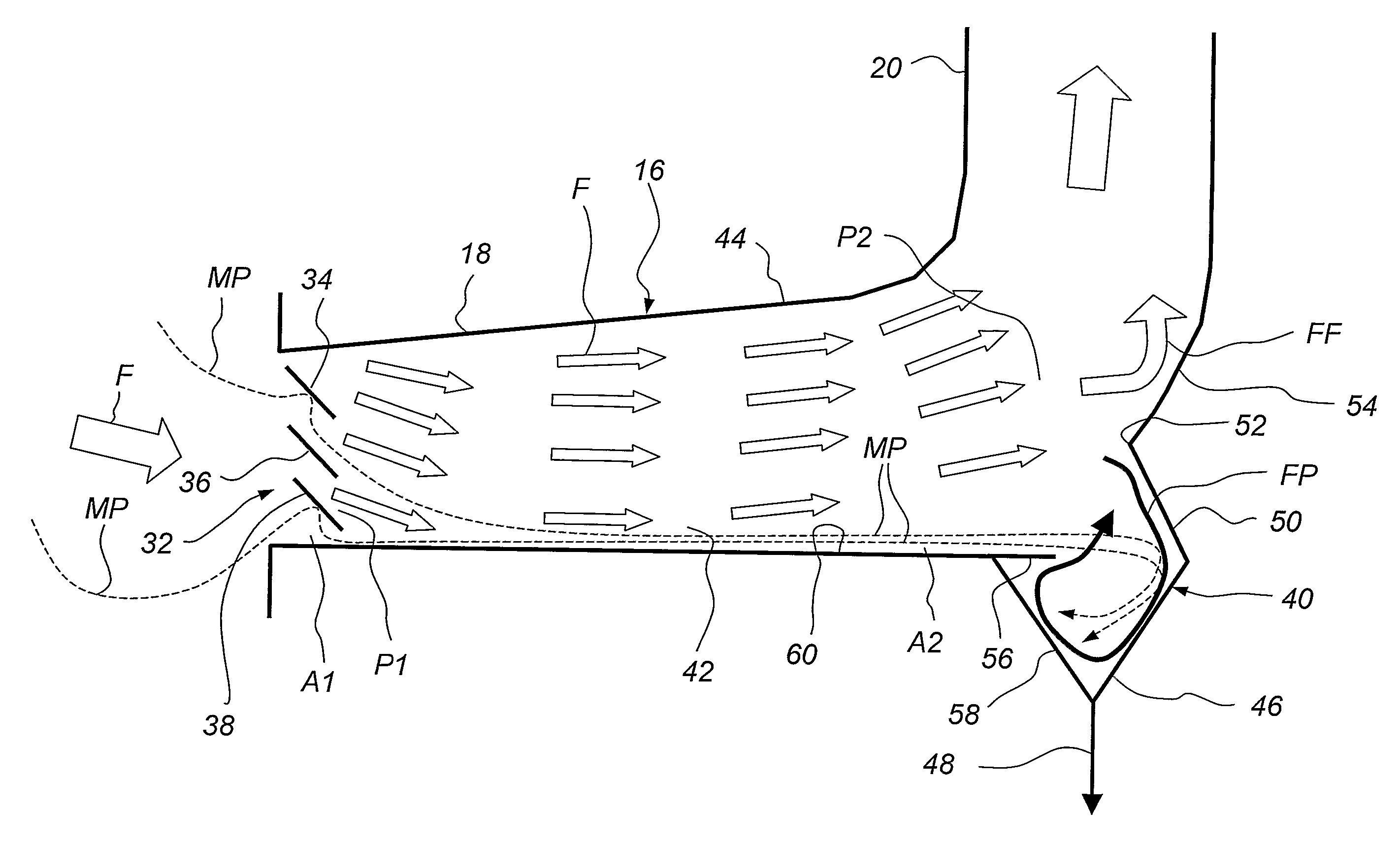
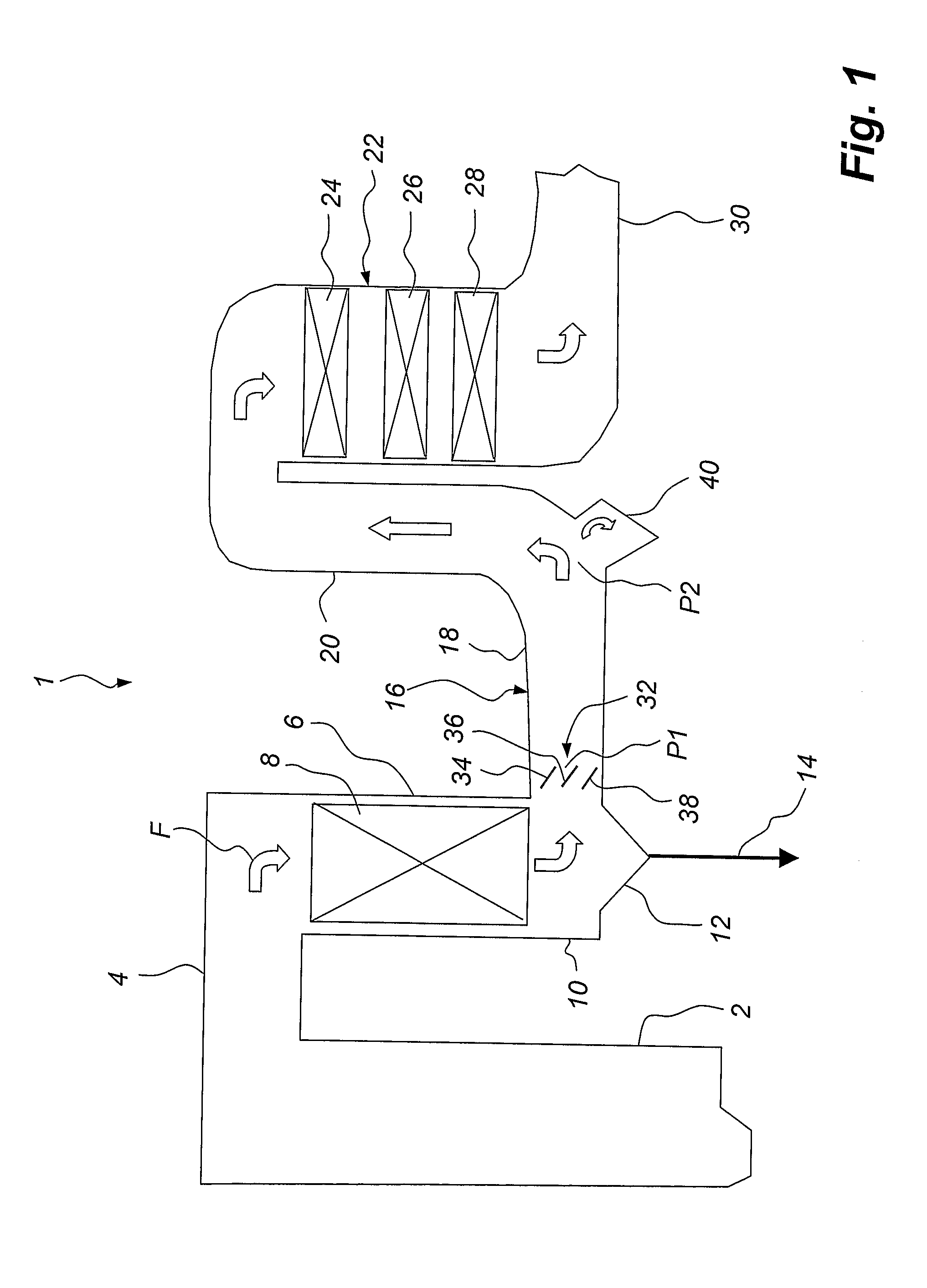
[0030]FIG. 1 shows a power station 1. The power station 1 has a boiler 2, in which a fuel, such as coal, oil or waste, is burnt by being contacted with supplied air. The flue gases F and the particles formed in the burning are passed through a duct 4 to a flue gas cooler, also referred to as an economiser, 6. In the flue gas cooler 6 heat is extracted from the flue gases as they are being passed vertically downwards through a package of tubes 8 and there being brought into indirect contact with the feed water of the boiler 2. The flue gas cooler 6 has in its lower portion 10 a dust hopper 12 which collects some coarse particles. A discharge device 14 is used to remove such collected coarse particles. In the lower portion 10 of the flue gas cooler 6, the flue gases change from a vertical direction of flow to a horizontal direction of flow and are passed into a device 16 according to the invention.

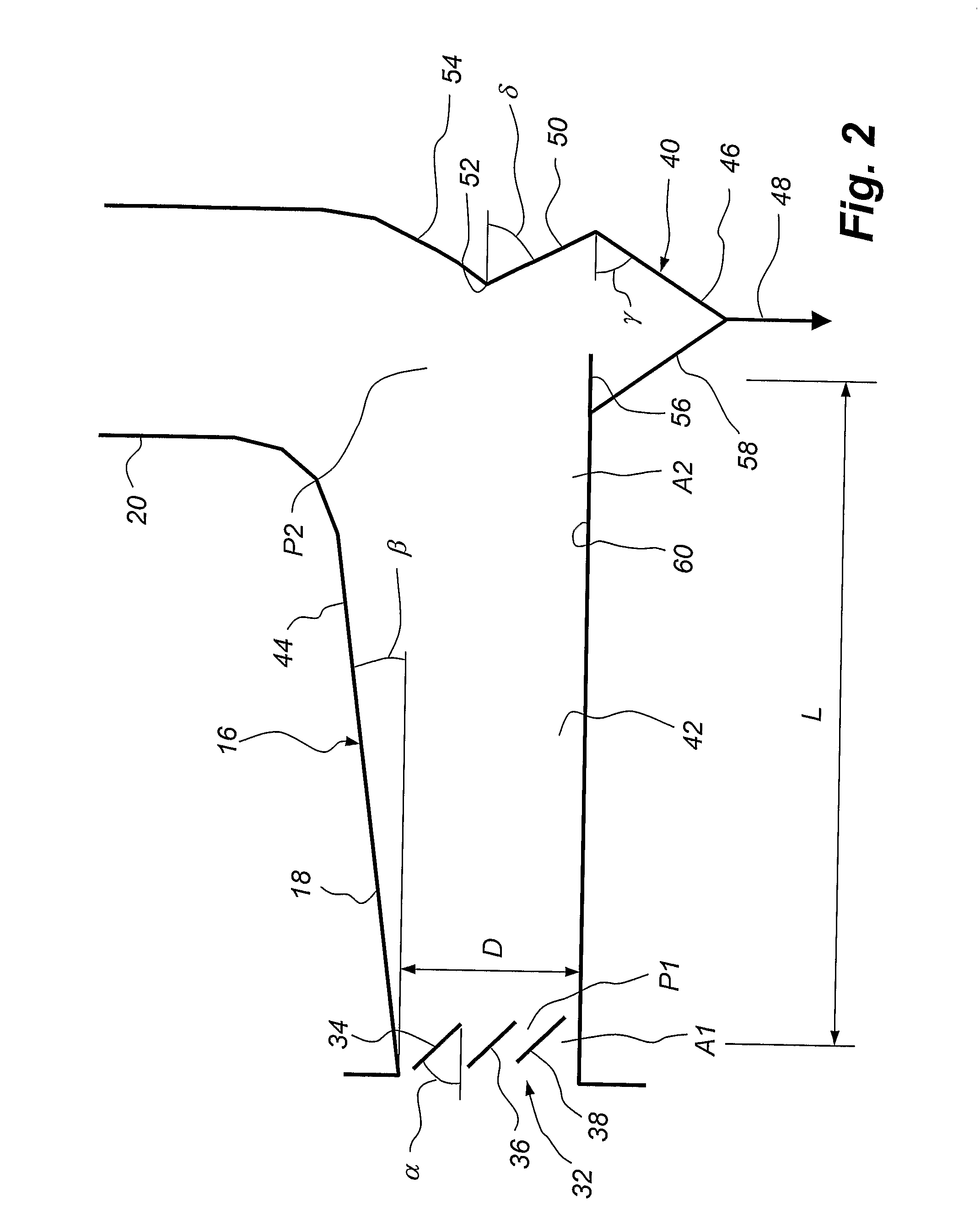
[0031] The device 16 has a horizontal flue gas duct 18, which passes the flue gases in ...


PUM

PropertyMeasurementUnit
angleaaaaaaaaaa
angleaaaaaaaaaa
angleaaaaaaaaaa

Abstract

A device (16) for separating particles (MP) from a flue gas flow (F) has a horizontal flue gas duct (18), through which the flue gas flow (F) is passed substantially horizontally from a first position (P1) to a second position (P2). In the first position (P1), the device (16) has a baffle arrangement (32), which comprises at least one plate (34, 36, 38) which is arranged in the flue gas duct (18) and which is inclined so as to deflect particles (MP) down to the lower portion (42) of the horizontal flue gas duct (18). In the second position (P2), the device (16) has a collecting means (40), which is arranged in the lower portion (42) of the flue gas duct (18) to collect the particles (MP) which have been deflected downwards by the plate (34, 36, 38) to the lower portion (42) of the flue gas duct (18).

Description

FIELD OF THE INVENTION [0001] The present invention relates to a method for separating particles from a flue gas flow which is passed substantially horizontally in a flue gas duct from a first position to a second position. [0002] The present invention also relates to a device for separating particles from a flue gas flow, which device has a horizontal flue gas duct, through which flue gas is passed substantially horizontally from a first position to a second position. BACKGROUND ART [0003] Flue gas cleaning plants for, inter alia, coal-fired and oil-fired power stations, waste incineration plants etc. often have what is referred to as an SCR reactor. An SCR (Selective Catalytic Reduction) reactor involves a reactor in which a catalytically induced, selective reduction of nitrogen oxides occurs. The SCR reactor has a catalyst, which often is configured as a honeycomb structure or as a number of closely spaced plates to provide a maximum reactive surface. A drawback in many SCR react...

Claims


Application Information

Patent Timeline
Patent Type & Authority Applications(United States)
IPC IPC(8): B01D45/02B01D45/06F23J15/02B01DB01D45/04B01D45/08F23J1/00
CPCB01D45/04B01D45/08F23J2217/20F23J1/00F23J15/022B03C3/363
Inventor ANDERSSON, RUNE
Owner GENERAL ELECTRIC TECH GMBH
Why Eureka
Try Eureka