Check valve

a check valve and valve body technology, applied in the field of check valves, can solve the problems of large mass that must be moved, valves that cannot react quickly enough to high-frequency actuation, and are unsuitable for completely automated assembly, and achieve the effect of low cost and minimal spa

Inactive Publication Date: 2008-02-07
ZF FRIEDRICHSHAFEN AG
View PDF7 Cites 54 Cited by
  • Summary
  • Abstract
  • Description
  • Claims
  • Application Information

AI Technical Summary

Benefits of technology

[0006]An object of the invention is to create a low-noise check valve which can be actuated at high frequency, which occupies a minimum of space, and which can be produced at low cost under mass production conditions.
[0008]It is advantageous here that a ball is used as the valve body and that this ball is guided with precision between the guide ribs. The retaining element, in the form of a contoured spring disk with an opening in the center, acts on the ball in such a way that it can open the valve against the force of the spring, but is limited in its stroke at the same time. To minimize noise, the stroke of the ball is also limited elastically.
[0011]According to another embodiment, the retaining element has at least one radially inward-directed spring tongue, which keeps the valve body under elastic pretension. It is advantageous here that the spring tongue is also an integral part of the retaining element, so that the projections, the spring tongue, and the retaining element can be produced out of a single piece of material. To ensure that the flow is throttled to the least possible extent, the guide ribs extend axially over only part of the bore. It is advantageous here for the guide ribs to have a free area underneath the retaining element, so that the fluid can flow smoothly through the check valve.
[0012]According to another embodiment, the retaining element is held positively in place in the housing. It is advantageous here to hold the retaining element positively in place by peening-over parts of the material of the housing.
[0020]It is advantageous for the spring tongue to be in the form of a circle or spiral so that a softer spring characteristic can be obtained.

Problems solved by technology

Check valves of this design, especially those with a valve ball or a segment of a ball, operate very precisely in principle, but their disadvantage is that a large mass must be moved, and the valve thus cannot react quickly enough for high-frequency actuations.
This design also occupies a considerable amount of space and, simply because of the number of individual parts and their shapes, it is unsuitable for completely automated assembly.

Method used


Image

  • Check valve
  • Check valve
  • Check valve

Examples


Embodiment Construction

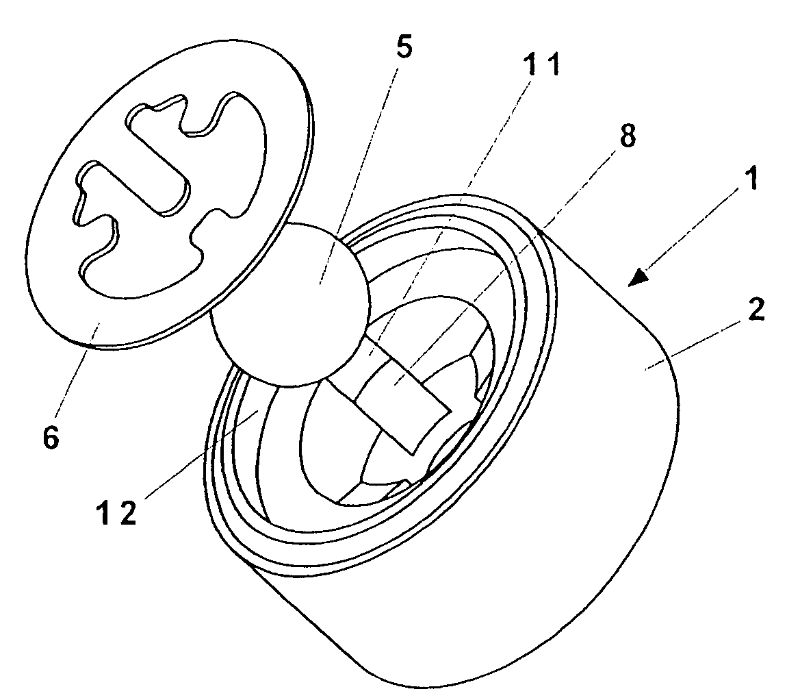
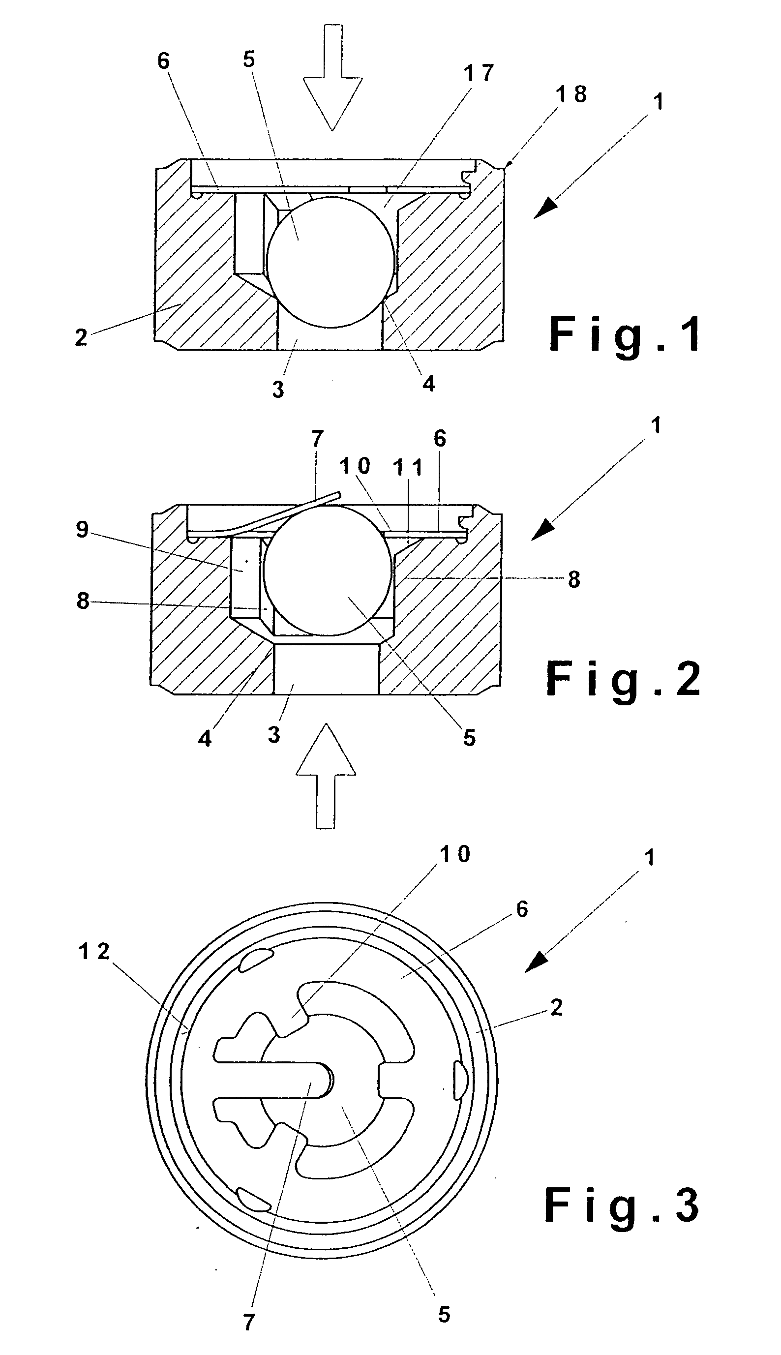
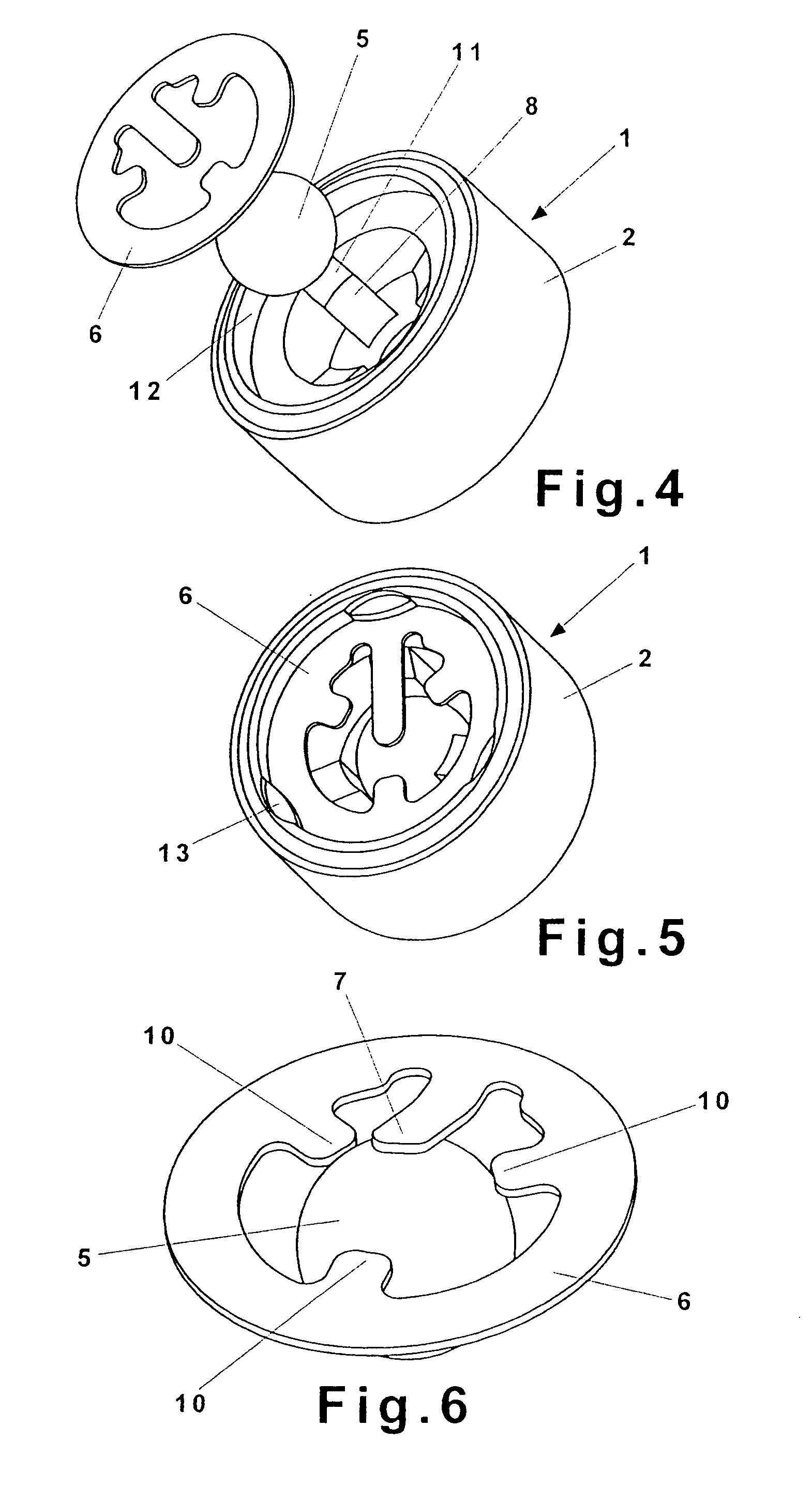
[0031]FIG. 1 shows the check valve 1 with a housing 2, which preferably can be produced without any undercuts, i.e., as-molded, without the need for any finish machining, ready for use just as it comes from the mold. A sintering or pressing technique is preferred for the production of this housing.

[0032]The housing 2 has a central inflow bore 3, which forms the valve seat 4 at the transition to the bore 17. In the area of its valve seat 4, the inflow bore 3 is closed by the valve body 5, designed as a ball. Above the valve body 5 there is a retaining element 6, in the form of an internally contoured spring disk, which is arranged in such a way that its outer edge is permanently connected to the housing 2, while its inner area exerts elastic force either directly or at least approximately on the center of the valve body 5.

[0033]The housing 2 has a cutting edge 18 on at least one end surface, which allows it to be installed tightly in a receiving bore.

[0034]FIG. 2 shows the check valv...


PUM


Abstract

Check valve includes a housing, a bore, and a movable valve body, which is spring-loaded and rests with a sealing action on a valve seat, where the bore is designed as a stepped bore, where the bore with the smaller diameter has the valve seat, and where the bore with the larger diameter holds the movable valve element. The valve body is designed as a ball, which is guided in the bore by at least two guide ribs, and a retaining element in the terminal area of the bore captures the ball and simultaneously spring-loads it.

Description

BACKGROUND OF THE INVENTION[0001]1. Field of the Invention[0002]The invention pertains to a check valve, consisting of a housing, a bore, and a movable valve body, which is spring-loaded and rests with a sealing action on a valve seat, where the bore is designed as a stepped bore, and where the bore with the smaller diameter has the valve seat and the bore with the larger diameter holds the movable valve element.[0003]2. Description of the Related Art[0004]Check valves are already known (DE 40 25 488 C2) in which a movable valve element is provided, where a ball-shaped valve body is provided at least in the area of the valve seat. A closing spring keeps this valve body under pretension. A movable cylindrical part and a stationary cylindrical part, furthermore, create an annular space, the volume of which changes with the movement of the inner parts. The action of the valve can thus be damped by way of a throttle bore. Check valves of this design, especially those with a valve ball o...

Claims


Application Information

Patent Timeline
Patent Type & Authority Applications(United States)
IPC IPC(8): F16K15/04
CPCF16K15/046Y10T137/7937Y10T137/7927
Inventor BECK, HUBERT
Owner ZF FRIEDRICHSHAFEN AG
Why Eureka
Try Eureka