
Method for Improved Well Control With A Downhole Device

a well control and downhole technology, applied in the field of systems and methods for well control, can solve problems such as damage to the well or interruption of work activities

Active Publication Date: 2008-02-07
BAKER HUGHES INC
View PDF14 Cites 57 Cited by
  • Summary
  • Abstract
  • Description
  • Claims
  • Application Information

AI Technical Summary

Benefits of technology

[0008] In some embodiments, the well control device is configured to hydraulically isolate one or more sections of a wellbore. An exemplary well control device includes a pipe bore flow control device to selectively block fluid flow in a pipe bore, an annulus flow control device that selectively blocks fluid flow in a well annulus, and a bypass flow control device that selectively flows fluid from the pipe bore to the annulus. Depending on the settings of each of these flow devices, e.g., open, closed, or throttled, an out-of-norm condition associated with one or more of these isolated wellbore section can be treated independently, sequentially or concurrently. In embodiments, a surface controller and/or a downhole controller controls the well control device. A communication device provides one-way or bidirectional signal and/or data transfer between the controller(s), surface personnel and the well control device. In one arrangement, the surface controller transmits a downlink encoded with instructions for operating the well control device. The surface controller can also receive uplinks from the downhole controller that are encoded with data relating to sensor measurements, e.g., measured pressure, the operating status of the downhole well control device, or other such data. The downhole controller can be programmed to automatically control the well control device without downlink instructions and/or send uplink signals prior to activating or de-activating the well control device. Suitable communication devices can utilize flow variations, pressure pulses, EM signals, acoustic signals, signals conducted via metal or optical wires, and/or controlled manipulation of a work string. In one embodiment, the bypass valve may be used to generate pressure pulses and/or flow variations to transmit data to the surface.
[0009] One exemplary application of a well control device is to control a well kick. Upon detection of a kick, the well control device closes the pipe bore, seals off the annulus, and opens the bypass valve. Next, based on available information, e.g., surface/downhole measured pressure, a “kill” mud weight is determined and pumped into the wellbore. The open bypass valve allows circulation of the kill mud above the well control device to circulate out formation fluids that were not shut-in below the well control device. After the annulus above well control device is filled with the kill mud, the well control device is de-activated to provide normal flow through the pipe bore and annulus.
[0010] Another exemplary application of a well control device is to control drilling fluid being lost to the formation due to weak formations. After a loss is detected, the well control device is activated to stop flow in the annulus and pipe bore and the bypass valve is opened. If mud is lost above the well control device, lost circulation material (LCM) is circulated using the open bypass valve. After losses are cured, the well control device is de-activated. If mud is lost below the well control device, the entire annulus above the well control device is maintained full of mud to prevent a kick in the open hole section above the well control device and below a casing shoe. Next, cuttings are circulate

Problems solved by technology

Out-of-norm conditions also include conditions that could interrupt work activities or damage the well.

Method used


Image

  • Method for Improved Well Control With A Downhole Device
  • Method for Improved Well Control With A Downhole Device
  • Method for Improved Well Control With A Downhole Device

Examples


Embodiment Construction

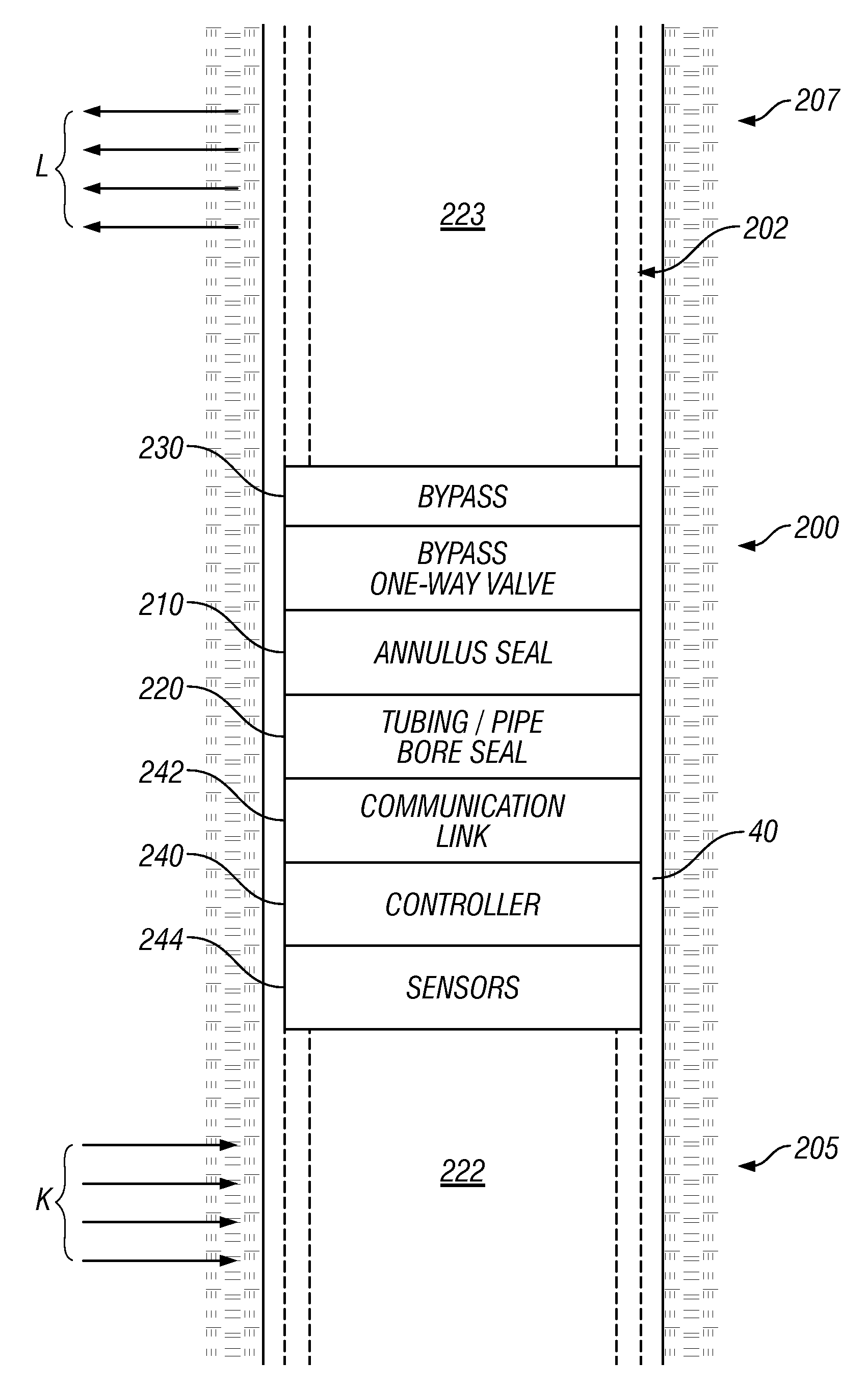
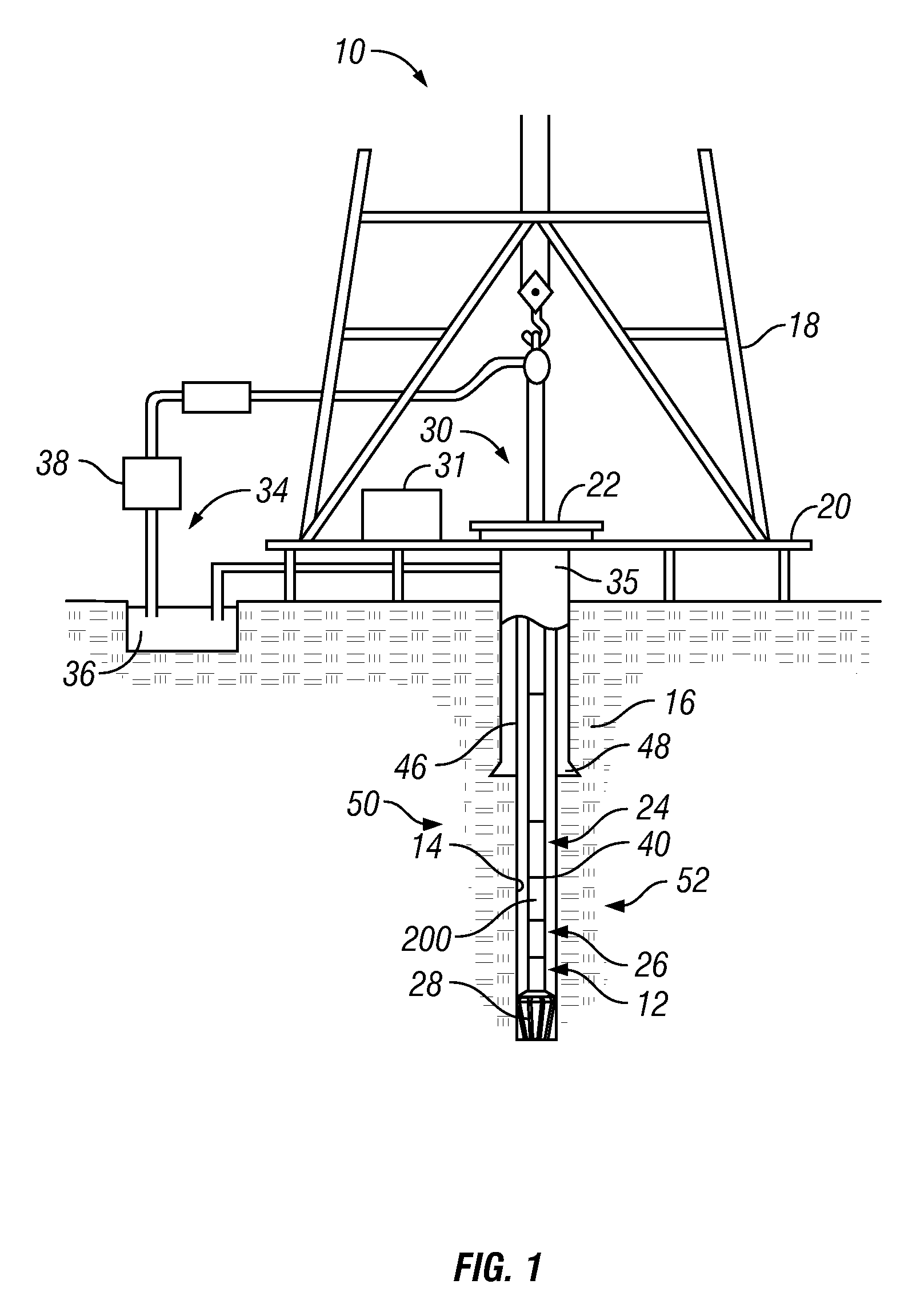
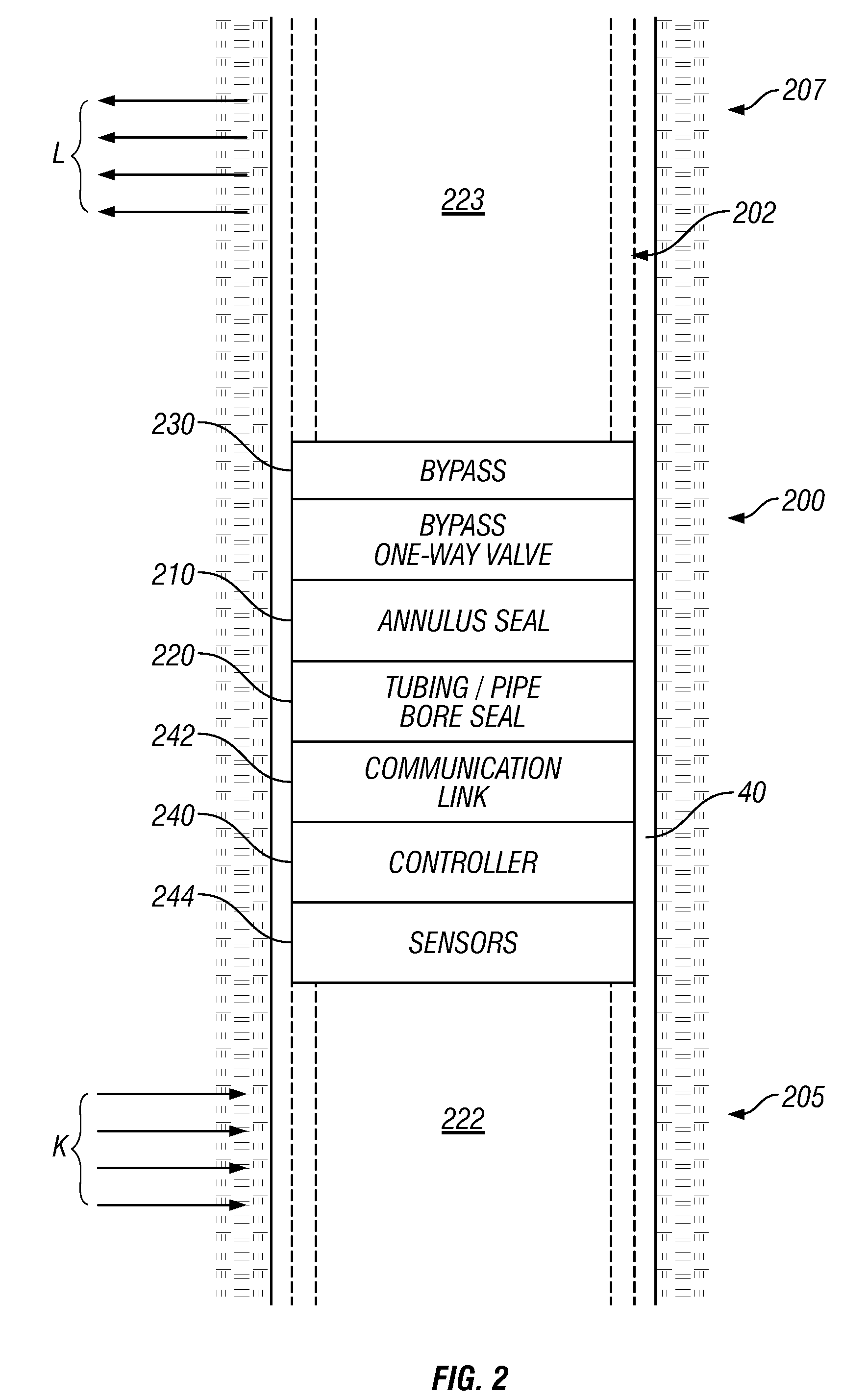
[0020] The present invention relates to devices and methods for control of fluid flow in a wellbore. The fluid may be a liquid, a gas, a slurry or mixtures of same. The present invention is susceptible to embodiments of different forms. There are shown in the drawings, and herein will be described in detail, specific embodiments of the present invention with the understanding that the present disclosure is to be considered an exemplification of the principles of the invention, and is not intended to limit the invention to that illustrated and described herein.

[0021] Referring initially to FIG. 1 there is shown a schematic diagram of a well construction system 10 having one or more well tools 12 shown conveyed in a borehole 14 formed in a formation 16. The system 10 can be configured for performing one or more operations related to the construction, logging, completion or work-over of a hydrocarbon producing well. In particular, FIG. 1 shows a schematic elevation view of one embodim...


PUM


Abstract

A drilling system includes a downhole well control device that can be used to control out-of-norm wellbore conditions. The downhole well control device can control one or more selected fluid parameters. The well control device in cooperation or independent of surface devices exerts control over one or more drilling or formation parameters to manage an out-of-norm wellbore condition. An exemplary well control device hydraulically isolates one or more sections of a wellbore by selectively blocking fluid flow in a pipe bore and an annulus. The control device also selectively flows fluid from the pipe bore to the annulus. A communication device provides on-way or bidirectional signal and / or data transfer between the controller(s), surface personnel and the well control device. Exemplary application of the well control device include controlling a well kick, controlling drilling fluid being lost to the formation and controlling a simultaneous kick and loss.

Description

CROSS-REFERENCE TO RELATED APPLICATIONS [0001] This application takes priority from U.S. Provisional Patent Application Ser. No. 60 / 818,071, filed Jun. 30, 2006.BACKGROUND OF THE INVENTION [0002] 1. Field of the Invention [0003] The present invention relates to systems and methods for well control during oilfield operations in situations such as kicks of formation fluids, mud losses and underground blowouts. [0004] 2. Description of the Related Art [0005] During construction or servicing of a hydrocarbon producing well, an operator can encounter a number of undesirable conditions that can pose a hazard to equipment and personnel. One undesirable condition is a “kick.” During drilling, a high pressure formation fluid can invade the well bore and displace drilling fluid from the well. The resulting pressure “kick” can lead to a well blow-out at the surface. Conventionally, during drilling, the mud weight of a drilling fluid circulated in the well is selected to provide a hydrostatic p...

Claims


Application Information

Patent Timeline
IPC IPC(8): E21B17/18E21B21/08
CPCE21B21/103E21B34/06E21B33/06
Inventor KRUEGER, SVENBRUNS, JENS UWE
Owner BAKER HUGHES INC
Features
  • Generate Ideas
  • Intellectual Property
  • Life Sciences
  • Materials
  • Tech Scout
  • Unparalleled Data Quality
  • Higher Quality Content
  • 60% Fewer Hallucinations
Learn More