Installation Method for Non-Slip Sanitary Flooring

a technology of installation method and sanitary flooring, which is applied in the direction of resiliently mounted floors, flooring, building components, etc., can solve the problems of not adhesion well to certain underlying surfaces, requiring sophisticated priming or being limited to certain surface materials, and joints that change the otherwise (usually) level flooring may be unacceptabl

Inactive Publication Date: 2008-02-07
MARTIN JOEL E JR +1
View PDF16 Cites 50 Cited by
  • Summary
  • Abstract
  • Description
  • Claims
  • Application Information

AI Technical Summary

Problems solved by technology

As potential disadvantages, however, materials applied as liquids typically require a finite drying time, may produce undesired (or even regulated) solvent vapors, may not stick well to certain underlying surfaces and may require sophisticated priming or be limited to certain surface materials.
Stated differently, merely placing individual PVC sheets on a floor does not complete the necessary sanitary arrangements because food can gather at the unsealed joints and in turn encourage the growth of unsanitary bacteria.
In flooring applications, however, joints that change the otherwise (usually) level flooring may be unacceptable.
Similarly, using profiles (i.e., additional structural pieces) to create the joint may be acceptable for some purposes, but can create a slight bump that is unacceptable in other circumstances.
For the same reasons, the types of reinforced and U-shaped joints that can be used to connect metal sheeting in non-flooring applications are generally unacceptable for kitchen or other sanitary flooring.
Although this technique has satisfactory applications, it requires both the routing and welding steps.
Because the seams are abutting, they also have a tendency to separate or potentially fail, leading to some of the safety and sanitary problems described above.

Method used


Image

  • Installation Method for Non-Slip Sanitary Flooring
  • Installation Method for Non-Slip Sanitary Flooring
  • Installation Method for Non-Slip Sanitary Flooring

Examples


Embodiment Construction

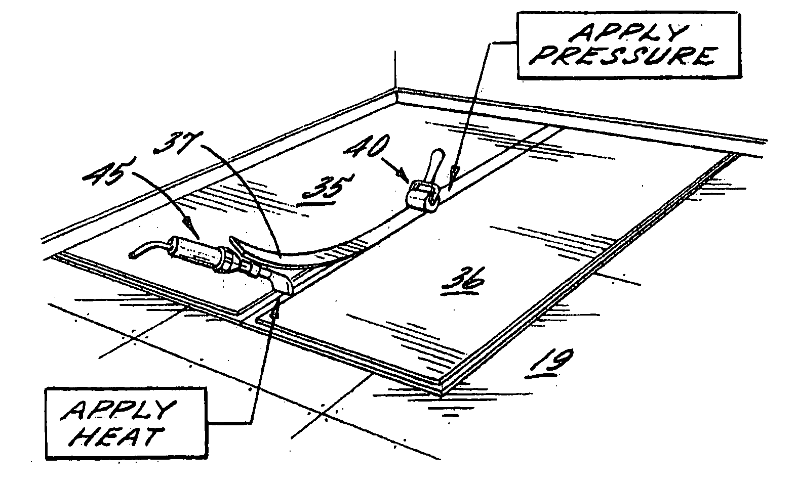
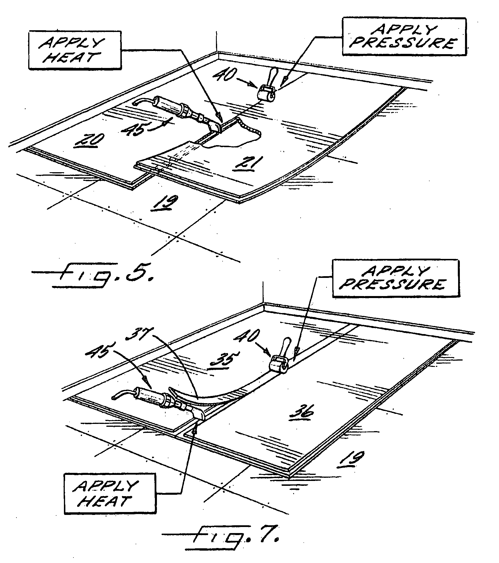
[0031] The invention is a method of joining non-slip (non-skid) polymer sheet flooring materials suitable for sanitary use in a manner that improves the quality of the resulting seam while minimizing the problems raised by joints in general and welded joints in particular.

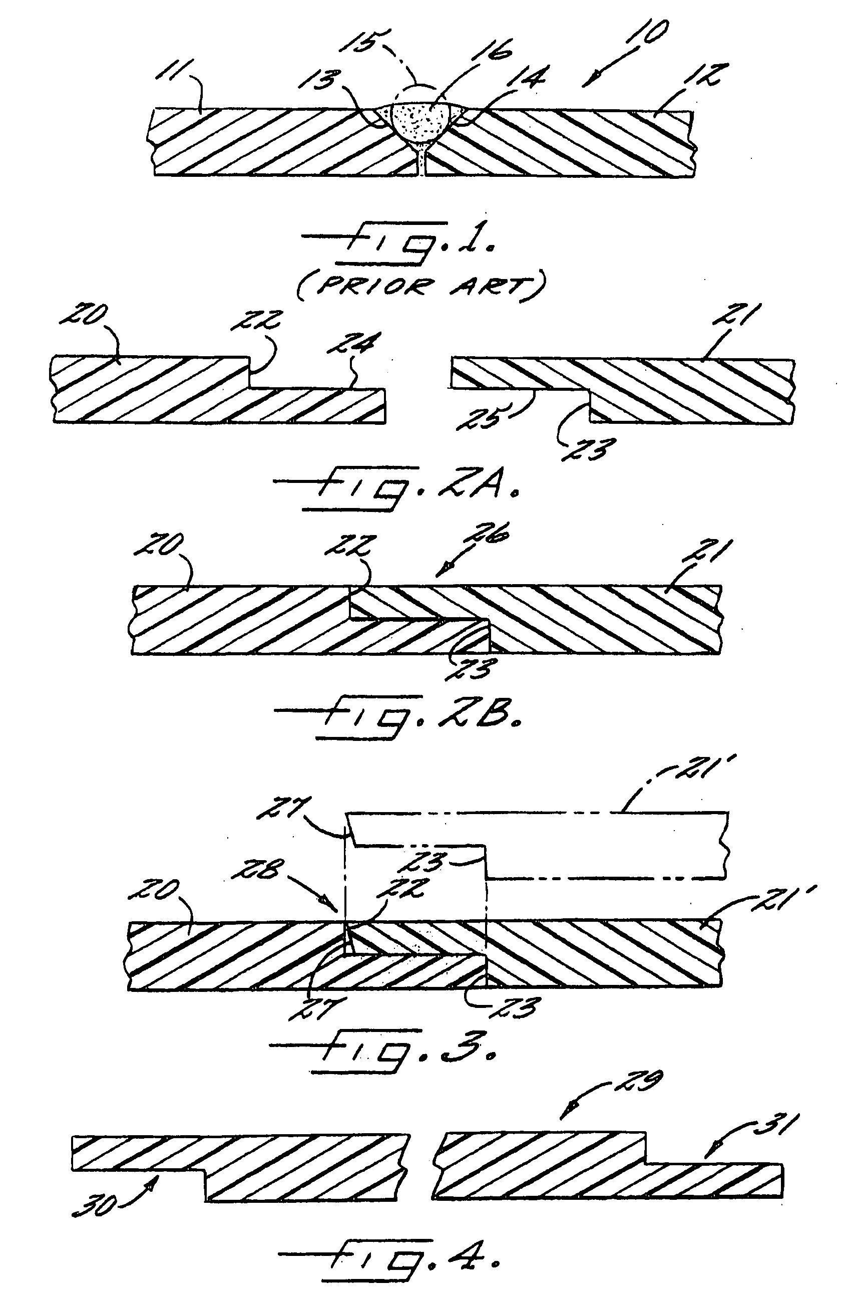
[0032] For background purposes, FIG. 1 illustrates a prior art joint broadly designated at 10. The joint is formed of respective portions 11 and 12 of polymer flooring, typically PVC as described earlier. In order to produce the joint 10, a router is used to cut enough material from each of the sheets 11 and 12 to define the respective oblique surfaces 13 and 14. A bead of welding material (usually, but not necessarily the same material as the flooring) indicated by the dotted circle 15 is applied between the surfaces 13 and 14 and melted to form the joint 16.

[0033]FIGS. 2A and 2B illustrate a step lap joint according to the present invention. The step lap joint is formed between respective first and second porti...


PUM

PropertyMeasurementUnit
lengthaaaaaaaaaa
lengthaaaaaaaaaa
widthaaaaaaaaaa

Abstract

A method of installing flooring and resulting structure are disclosed. The method is particularly useful for sanitary nonslip (or slip resistant) applications such as kitchens. The method includes the steps of positioning a first sheet of polymer flooring material with an upwardly-facing step cut along one edge of the first sheet on a floor to be covered, and applying a second sheet of polymer flooring material with a complementary downwardly-facing step cut along one edge of the second sheet to the upwardly facing step cut of the first sheet and to the floor adjacent the first sheet while concurrently sealing or bonding the respective faces to one another in a step lap joint.

Description

CROSS REFERENCE TO RELATED APPLICATIONS [0001] This application is a continuation-in-part application of pending U.S. application Ser. No. 11 / 456,747, filed Jul. 11, 2006, which is hereby incorporated by reference in its entirety.BACKGROUND [0002] The present invention relates to flooring materials and in particular relates to joints in certain types of polymer-based flooring materials that are used in non-slip (or “non-skid” or “slip resistant”) applications, sanitary applications, and applications in which both non-slip and sanitary characteristics are desired or necessary. [0003] Certain structural elements in commercial or other public establishments must meet the requirements of various local, state or federal codes. For example, a restaurant is typically governed by local health and sanitation codes, and if it meets certain other criteria, may also be subject to state and federal health and safety requirements such the Occupational Health and Safety Act (29 U.S.C. § 651 et seq...

Claims


Application Information

Patent Timeline
Patent Type & Authority Applications(United States)
IPC IPC(8): B23K11/00B65H69/08E04F13/16E04F15/22
CPCB29C65/04Y10T428/19B29C65/10B29C65/12B29C65/1425B29C65/5042B29C65/505B29C66/022B29C66/02241B29C66/1142B29C66/1162B29C66/1282B29C66/12841B29C66/14B29C66/43B29C66/721B29C66/836B29C66/8362B29C66/861B29C66/919B29C73/06B29C2073/264B29K2023/06B29K2023/12B29K2025/00B29K2027/06B29K2031/00B29K2055/02B29K2063/00B29K2067/00B29K2071/00B29K2071/12B29K2075/00B29K2077/00B29K2077/10B29K2081/06B29K2101/10B29K2101/12B29K2105/0845B29K2105/0854B29K2105/10B29K2105/12B29K2307/00B29K2309/08B29L2031/732E04F15/02E04F15/02005E04F15/16B29C65/08Y10T156/108B29C66/9161B29C66/91411B29C66/9141B29C65/4835B29C65/02B29C65/4815B29C65/00B29K2705/10B29K2705/12B29C66/7212B29C66/72143B29C66/72141B29C66/73921B29C66/73941E04F15/02172B29C66/71B29C66/712E04F15/02016B29K2307/04B29K2277/10B29K2069/00B29K2065/00B29K2061/04
Inventor MARTIN, JOEL E. JR.NEALE, RICHARD C. III
Owner MARTIN JOEL E JR
Why Eureka
Try Eureka