Self-pumping hydropneumatic spring strut with internal level control

US20080029939A1Inactive Publication Date: 2008-02-07ZF FRIEDRICHSHAFEN AG

Image

  • Self-pumping hydropneumatic spring strut with internal level control
  • Self-pumping hydropneumatic spring strut with internal level control
  • Self-pumping hydropneumatic spring strut with internal level control

Examples


Embodiment Construction

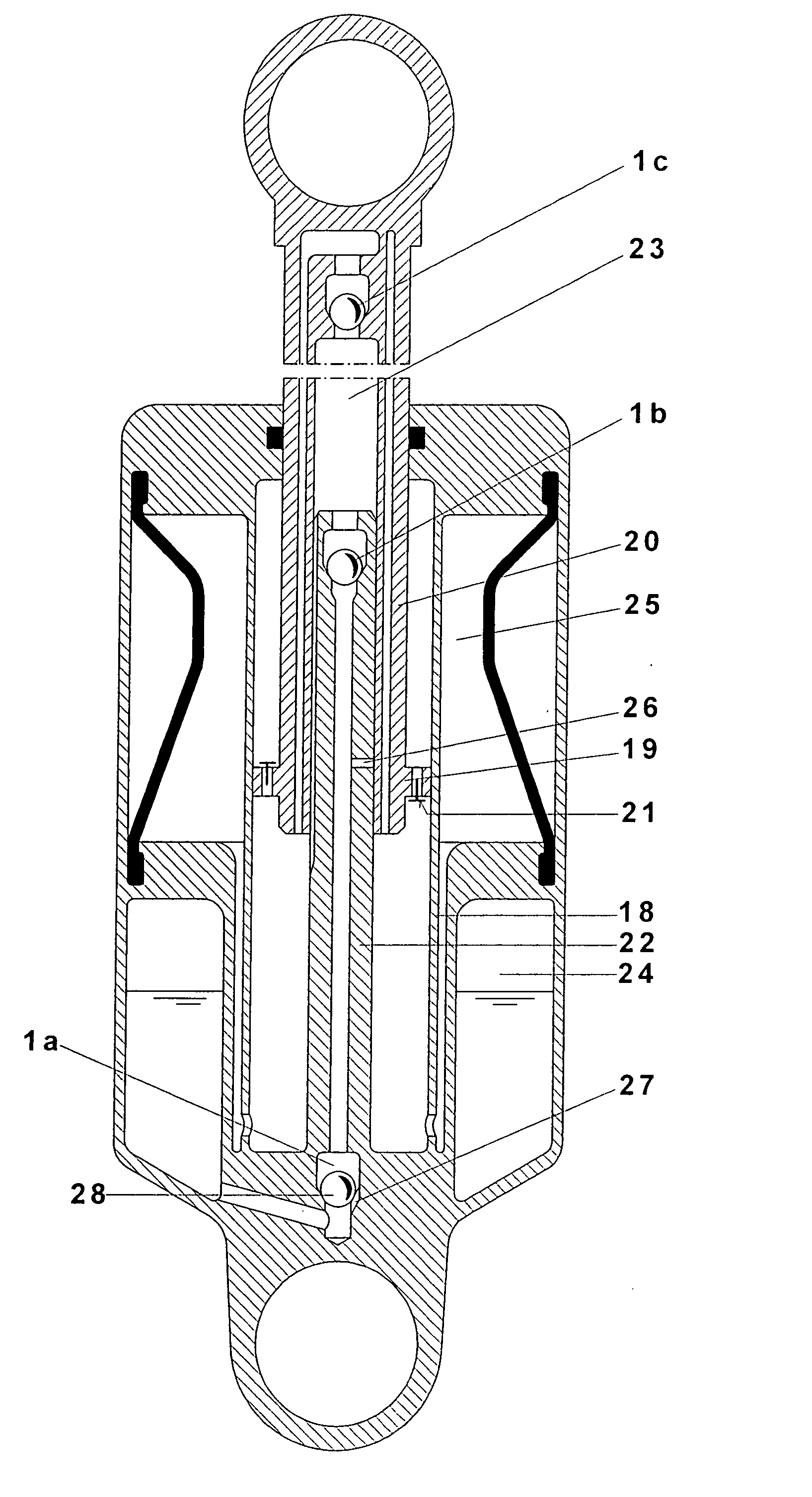
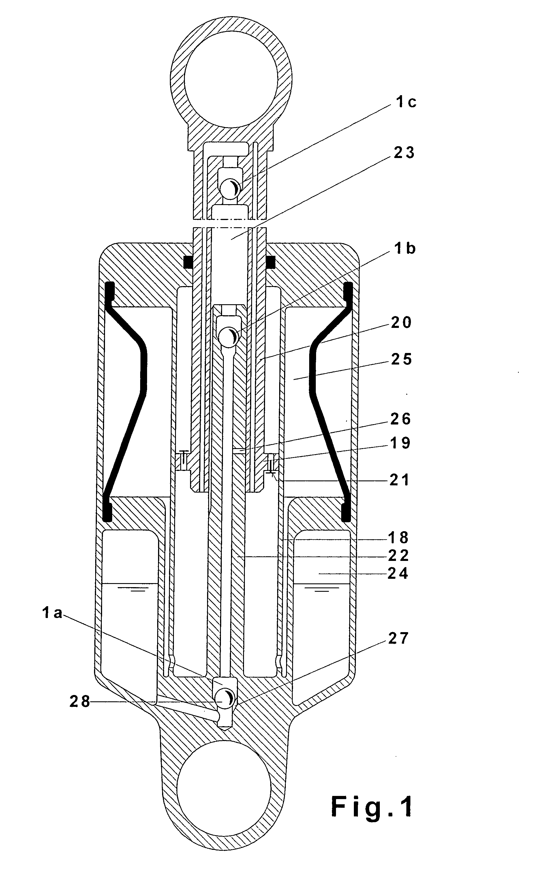
[0031]The spring strut for motor vehicles shown in FIG. 1 includes a the working cylinder 18, in which a piston 19, mounted on the end of a piston rod 20, slides. The working cylinder 18 is connected underneath the piston 19 to the high-pressure chamber 25. The unit is attached to the body of a vehicle and to the axle of the vehicle in a manner not shown in the figure. During the operation of the vehicle, the damping forces are generated by the damping valves 21.

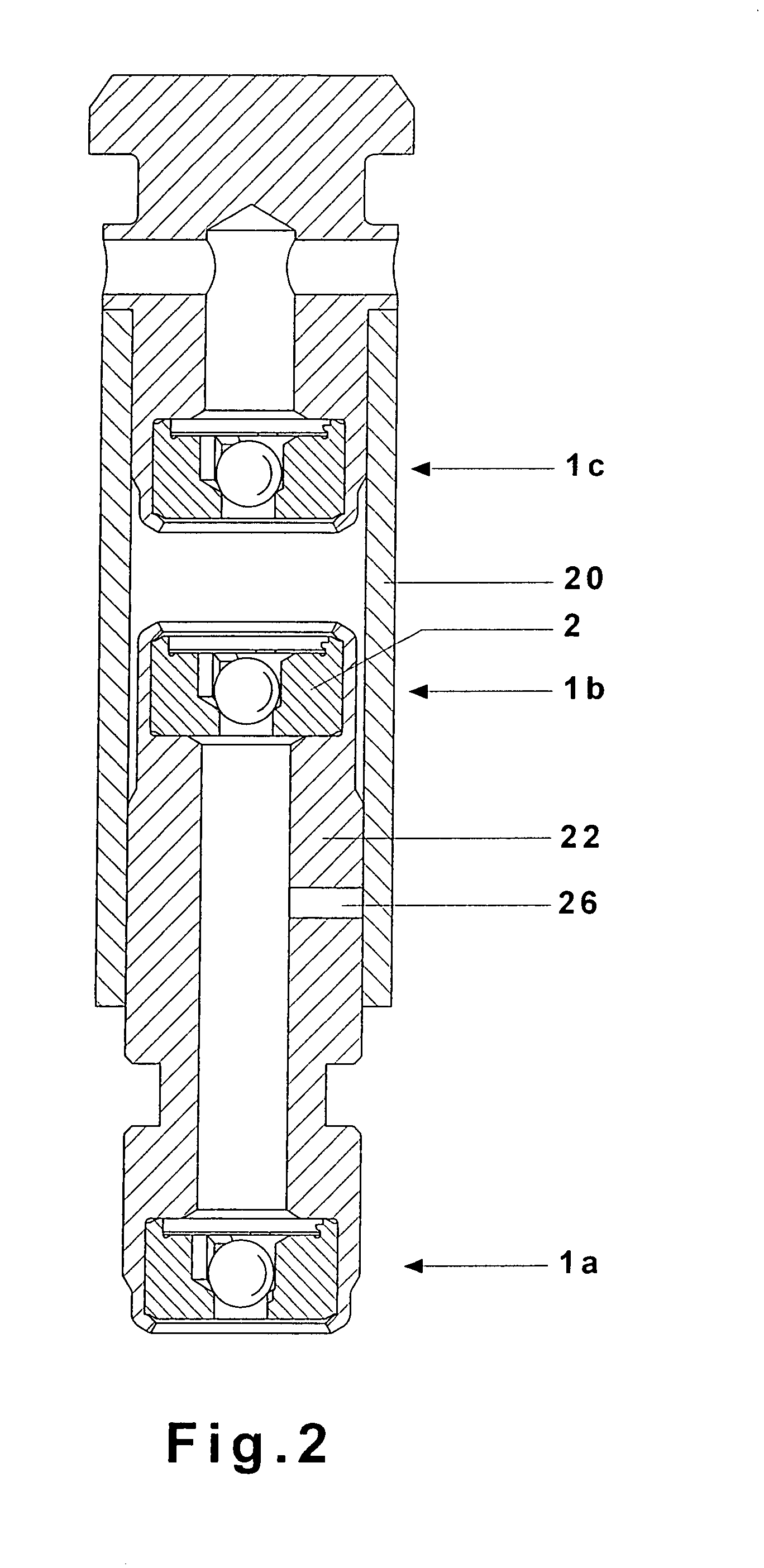
[0032]The spring strut according to FIG. 1 shows an oil pump, which consists of the pump rod 22 and the pump cylinder 23, which is formed by the hollow piston rod 20. The movements of the vehicle axle caused by irregularities in the pavement actuate this oil pump, which continuously conveys oil in a controlled manner through the suction valve 1b, out of the low-pressure chamber 24 via the outlet valve 1c into the working cylinder and thus into the high-pressure chamber 25. As a result, the piston 19 and the piston rod 20 are...


PUM


Abstract

An oil-filled working cylinder is divided into first and second working spaces by a working piston, the first working space being connected to a high pressure chamber. A piston pump includes a pump rod received in a pump cylinder formed by the hollow piston rod, the pump rod having a bore connected to a low pressure chamber via a discharge valve, a distal end provided with a suction valve, and a down-regulating opening connecting the bore to the first working space as a function of the position of the working piston, the pump cylinder being connected to the first working space by an outlet valve. At least one of the valves is a check valve including a housing having a bore, a ball reciprocably guided in the bore by guide ribs, and a resilient retaining element capturing the ball in the bore and spring-loading the ball toward a valve seat.

Description

BACKGROUND OF THE INVENTION[0001]1. Field of the Invention[0002]The invention pertains to a self-pumping hydropneumatic spring strut with internal level control, especially for motor vehicles, with an oil-filled working cylinder under the pressure of at least one gas cushion located in a high-pressure chamber and acting as a spring, the working cylinder being divided into two working spaces by a working piston carried by a hollow piston rod. A piston pump is driven by the movements of the spring and conveys oil from a low-pressure chamber into the working space connected to the high-pressure chamber, the pump cylinder of the piston pump being formed by the hollow piston rod, into which a hollow pump rod, which is attached to the working cylinder and carries at its forward end a suction valve, travels, the bore of the hollow pump rod being connected to the low-pressure chamber. A down-regulating opening can be closed as a function of the position of the working piston in the working ...

Claims


Application Information

Patent Timeline
07 Feb 2008
Publication
US20080029939A1
IPC
F16F9/14; B60G17/044
CPC
B60G17/044; F16F9/092; F16F9/063
Inventors
BECK, HUBERT; SCHMITZ, KLAUS