
Small-sized motor having ring-shaped field magnet

a small-sized, magnet-type technology, applied in the direction of magnetic circuit rotating parts, magnetic circuit shape/form/construction, cooling/ventilation arrangement, etc., can solve the problems of inefficiency, disadvantage in production cost and quality, and difficult positioning and fixing of illustrated motors, so as to reduce the generation of cogging torque without excessively lowering the motor torque

Active Publication Date: 2008-02-07
MABUCHI MOTOR
View PDF16 Cites 11 Cited by
  • Summary
  • Abstract
  • Description
  • Claims
  • Application Information

AI Technical Summary

Benefits of technology

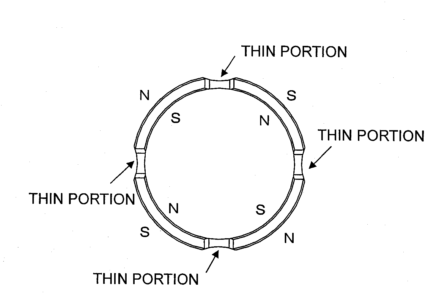
[0008]The present invention has been accomplished so as to solve the above-described problem, and an object of the present invention is to provide a small-sized motor which includes a multi-pole magnet having four or more poles and which can mitigate generation of cogging torque without excessively lowering motor torque.
[0009]Another object of the present invention is to provide a small-sized motor which enables a plurality of pole magnets to be assembled into a motor casing all together and firmly fixed thereto and which can reduce the volume of the magnet to thereby reduce cost.
[0011]According to the present invention, a constant gap can be maintained between the magnet and the rotor pole core, and, through formation of thin portions between the poles of the multi-pole magnet, generation of cogging torque can be mitigated, without excessively lowering the motor torque.
[0012]Moreover, since the magnet is formed into a ring-like shape as a whole, multiple poles can be readily formed on the magnet. In addition, this multi-pole magnet can be assembled into the motor casing as a single member and firmly fixed thereto. Thus, ease of assembly and productivity can be improved, whereby cost can be lowered.

Problems solved by technology

However, since the illustrated motor requires an operation of assembling a plurality of (two) C-shaped magnets into the yoke, particularly when four or more magnets are assembled into the yoke, their positioning and fixing are difficult.
That is, the structure of the illustrated motor is disadvantageous in terms of production cost and quality.
However, such a shape reduces the magnetic flux generated by use of an excessively large magnet by widening the gap, and therefore is not efficient.

Method used


Image

  • Small-sized motor having ring-shaped field magnet
  • Small-sized motor having ring-shaped field magnet
  • Small-sized motor having ring-shaped field magnet

Examples


examples

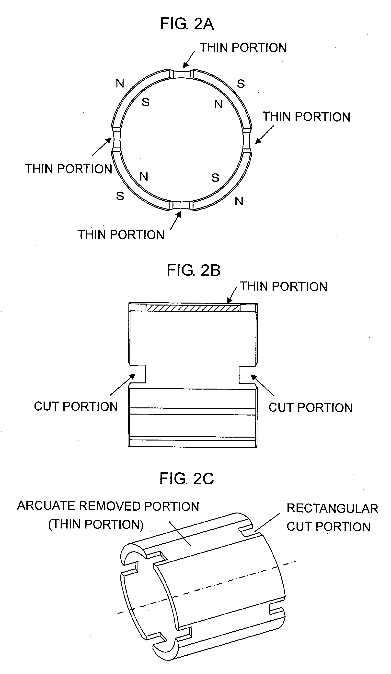
[0034]FIGS. 4A to 9B are views showing various example structures of the ring-shaped magnet. FIGS. 4A and 4B show examples structures of a magnet having four field poles in which, at each of central portions between the magnetic poles, the magnet is arcuately cut from the radially outward side to thereby form a thin portion. However, the above-described cut portions are not provided. FIG. 4A shows an example in which the four removed portions (thin portions) between the four magnetic poles have the same shape, and FIG. 4B shows an example in which the four removed portions (thin portions) have different shapes. That is, FIG. 4B shows an example in which large removed portions (arcuately removed portions) and small removed portions (arcuately removed portions) are alternately disposed in the circumferential direction.

[0035]The thin portions are not necessarily required to extend over the entire length of the magnet (in the thrust direction). As shown in FIGS. 5A and 5B, a wall portio...


PUM


Abstract

A small-sized motor includes a field magnet attached to an inner circumferential surface of a metallic motor casing and having four or more magnetic poles. The field magnet is formed of a single ring-shaped magnet member having a predetermined thickness with respect to the radial direction and a predetermined length with respect to the thrust direction. At each of portions between the magnetic poles formed through magnetization, the magnet member has a thin portion having a reduced thickness with respect to the radial direction, the thin portion being formed by cutting the magnet member from the radially outward side. The magnetization is performed in the radial direction so as to alternately form S poles and N poles in the circumferential direction. At each of portions between the magnetic poles, the magnet member may have cut portions formed at opposite end portions of the magnet member with respect to the thrust direction.

Description

BACKGROUND OF THE INVENTION[0001]1. Field of the Invention[0002]The present invention relates to a small-sized motor for use in, for example, power tools and electric equipment for vehicles such as door locks and seat adjusters, and more particularly to a structure of a magnet for stator magnetic poles attached to the inner circumferential surface of a motor casing.[0003]2. Description of the Related Art[0004]FIG. 11 is a cross sectional view of a conventional small-sized motor as shown in Japanese Patent Application Laid-Open (kokai) No. H10-201206. This motor includes a rotor having three magnetic poles; a yoke disposed to surround the rotor; and two stator pole magnets attached to the inner surface of the yoke and each having an arcuate (C-shaped) cross section. Each of the magnets has such a shape that the gap between the magnet and the outer circumferential surface of the rotor gradually increases from a central portion to opposite end portions along the circumferential directi...

Claims


Application Information

Patent Timeline
Patent Type & Authority Applications(United States)
IPC IPC(8): H02K1/27
CPCH02K23/04H02K1/17
Inventor IIZUKA, SATOSHIKINOSHITA, MITSUSHI
Owner MABUCHI MOTOR
Learn More