Method of Improving Medical Apparatus in Order to Replace Ancillary Medical Assistance by Employing Audible Verbal Human Sounding Voices to Prompt Therapeutic Usage and Provide Guidance, Measurements, Encouragement and Response, As Needed, to the Patient, By Using Electronic Technology

Inactive Publication Date: 2008-02-07
BRYANT TERRY KEITH
15 Cites 41 Cited by

AI-Extracted Technical Summary

Problems solved by technology

For instance, during recuperation after surgery a patient is required to repeatedly use ventilators with special gases to help moisturize the lungs, that during an operation usually collapse.
It may only be to start the patient out, which takes guidance or it may be to oversee the p...

Method used

[0049]FIG. 5 Shows an Alternative Embodiment of Present Invention. Referring to FIG. 5, this Alternative Embodiment of Present Invention shows the Audible Response Unit 1 connected as it is in FIG. 1 except with no connection to a Gauge within Medical Apparatus 11. In this embodiment, there is no gauge that provides information to the Audible Response Unit 1. The Medical Apparatus Constructed by Constructor without Gauge 11 in FIG. 3 may or may not have a gauge to measure some parameter of interest, but that gauge information is not provided to the Audible Response Unit 1. In this Alternative Embodiment, the Apparatus 11 is used in conjunction with the Audible Response Unit 1 in a way that the Audible Response Unit 1 provides therapeutic guidance audio information on Apparatus Operation to the operator of the Apparatus 11, therapeutic guidance audio information to cause the use of the Apparatus 11 according to a programmed schedule of time, and provides therapeutic guidance audio information so as to cause the repetitive use of the Apparatus 11 as required for proper use of the Apparatus. The Audible Response Unit 1 provides the therapeutic guidance audio information to the operator of the Apparatus 11 in order to eliminate the need for ancillary assistance, and in order to cause the proper use of the Apparatus 11 so as to provide maximum benefit from its use.
[0053] 2) replacing the normal human voice commands, responses, word, words, phrases or measurements that ancillary medical personnel normally provide to the patient, relating in relationship to medical apparatus with a human sounding electronically programmed voice or voices, giving the same basic therapeutic program requirements with adequate performance from the apparatus itself or within the range for providing the function of the medical apparatus being utilized, to prompt the patient to use the medical apparatus, as well as, guide the patient through the proper steps of using said medical apparatus, in order to fulfill the patient's therapeutic regiment that is required in order to encourage recovery;
[0054] 3) replacing the normal human visual readings or measurements that are produced by medical apparatus and read by ancillary medical personnel to facilitate the function of the medical apparatus with a human sounding electronically programmed voice or voices giving the same readings or measurements as deemed necessary to provide the patient with adequate information to fulfill the patient's therapeutic regiment for recovery;
[0089] 17) said digital program defining a set of predetermined set of controls and functions relating sensor output signals to audible verbal commands, responses and measurements, comprises of improving medical conditions of the patient through t...

Benefits of technology

[0021] To expedite said usage at the prescribed times, the present invention will not only benefit the Medical Industry by supplying an audible, verbal, simulated humanlike voice, which will prompt, encourage, and inform the patient, or person using their particular medical apparatus, but it will also help decrease the recuperation time of the patient, by continually reminding the patient until the performed requirements required by that apparatus being used are met. Another, important function of the present invention through the technology available is to provide a way to retrieve data form the medical apparatus's which can be stored or recorded for viewing at a later time to provide the necessary monitoring and diagnosis according to those particular reading retrieved, however this is not required for the completion of the concept, rather an added advantage.
[0022] Another, added advantage, to the present invention is the ability to retrieve data from the medical apparatus from a base station through radio frequencies, or whatever technology allows such performance, such as a palm pilot or CP, that provide information without the doctor having to be present at the location of the patient or user. This function provided by the present invention confirms a well known principle valued by the medical profession that, “the more one uses the prescribed treatment, the faster one recuperates.” With the conception of the present invention a new step in medical progress will be made, as the patient will be using...

Abstract

This method comprises of a method of eliminating ancillary medical assistance by the utilization of audible, verbal simulated human sounding voices produced by electronic technology which allows the ability to supply audible, verbal instructional help, prompting, measurements and also respond to the actions the patient is taking, through a human sounding voice providing the therapeutic requirements of the medical apparatus itself. With the employment of this unique method of self instructing, electronically functioning medical apparatus, the present invention will provide assistance to both the patient and the doctor by supplying non-human assistance, and will allow the therapeutic procedures contained within the electronic hardware of the present invention to be attached to, or built within, or combined to accommodate usage of each medical apparatus, thus, eliminating the need for ancillary medical assistance.

Application Domain

Technology Topic

Self directionMedical equipment +5

Image

  • Method of Improving Medical Apparatus in Order to Replace Ancillary Medical Assistance by Employing Audible Verbal Human Sounding Voices to Prompt Therapeutic Usage and Provide Guidance, Measurements, Encouragement and Response, As Needed, to the Patient, By Using Electronic Technology
  • Method of Improving Medical Apparatus in Order to Replace Ancillary Medical Assistance by Employing Audible Verbal Human Sounding Voices to Prompt Therapeutic Usage and Provide Guidance, Measurements, Encouragement and Response, As Needed, to the Patient, By Using Electronic Technology
  • Method of Improving Medical Apparatus in Order to Replace Ancillary Medical Assistance by Employing Audible Verbal Human Sounding Voices to Prompt Therapeutic Usage and Provide Guidance, Measurements, Encouragement and Response, As Needed, to the Patient, By Using Electronic Technology

Examples

  • Experimental program(1)

Example

BRIEF DESCRIPTION OF THE DRAWINGS
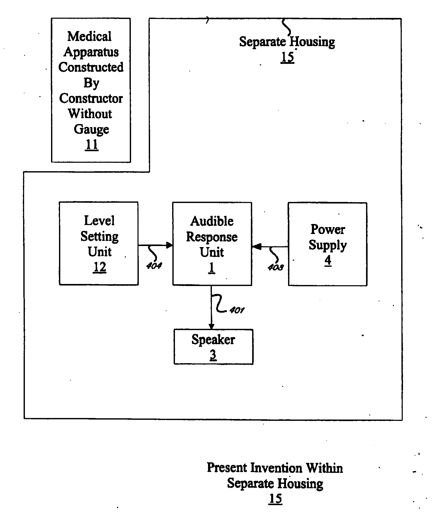
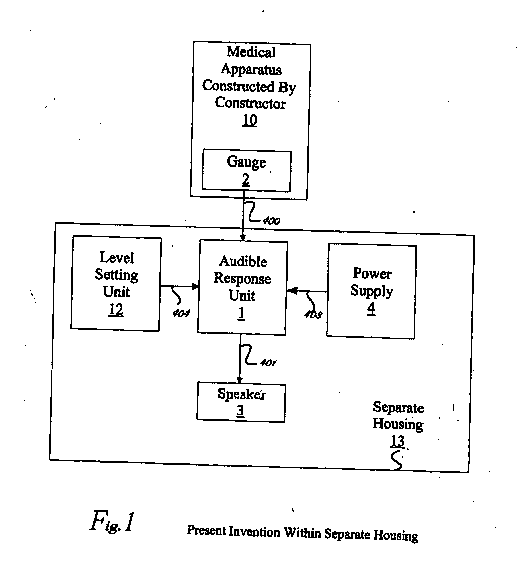
[0028]FIG. 1 Shows Preferred Embodiment of Present Invention. The present invention is enclosed within a separate housing 13 that does not include the Medical Apparatus Constructed by Constructor 10 and is comprised of Level Setting Unit 12, Audible Response Unit 1, Power Supply 4, and Speaker 3. A Gauge 2 within the Medical Apparatus Constructed By Constructor 10 connects to Audible Response Unit1 through one or more electrical connections labeled 400. A Level Setting Unit 12 connects to the Audible Response Unit 1 through one or more electrical connections labeled 404. Audible Response Unit connects to Speaker 3 through an electrical connection labeled 401. Power is supplied from Power Supply 4 to Audible Response Unit 1 through an electrical connection labeled 403.
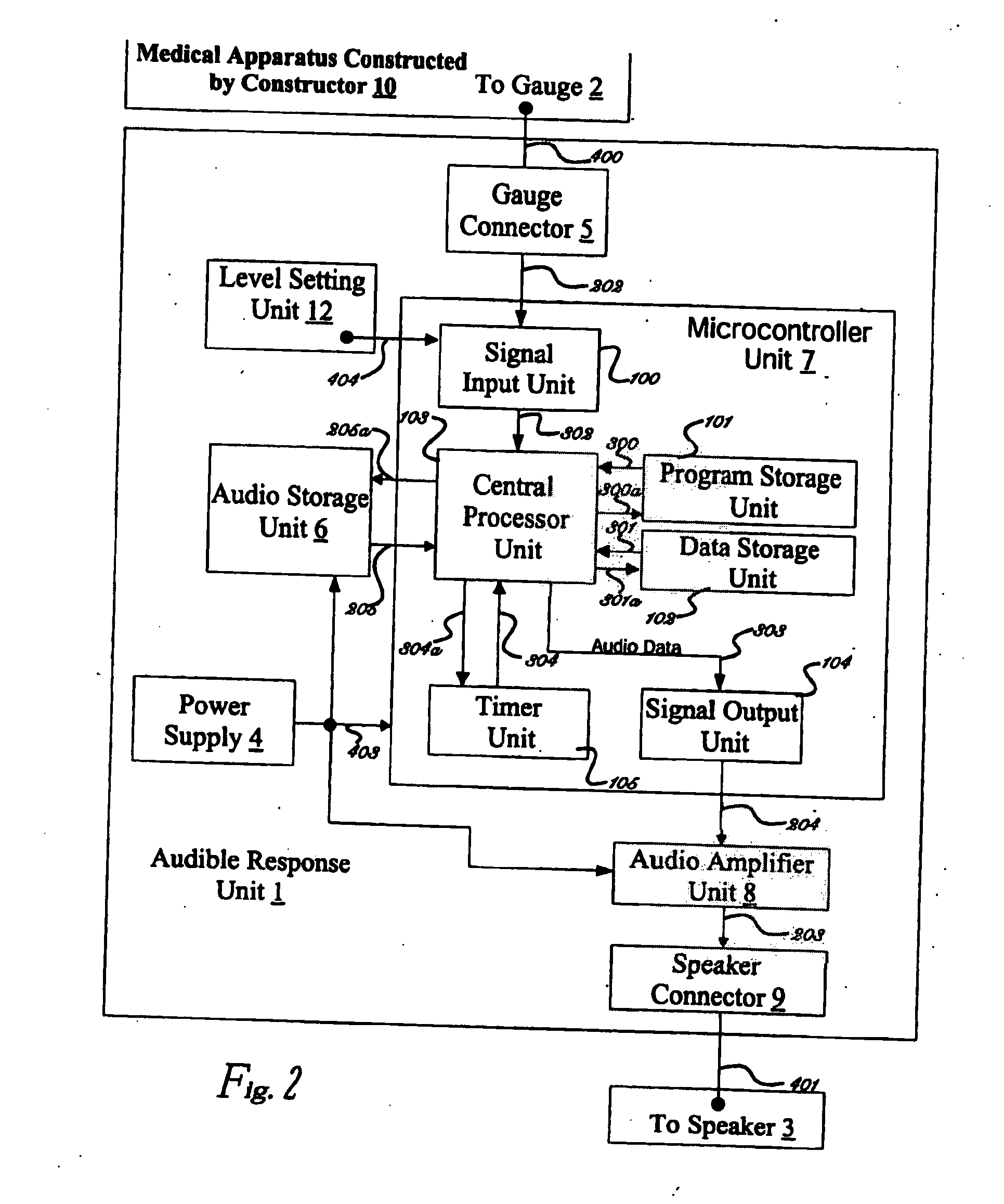
[0029]FIG. 2 shows the details of the Preferred Embodiment of Audible Response Unit 1 of FIG. 1 in relation to Medical Apparatus 10 and Speaker 3. Gauge 2 of Medical Apparatus 10 connects to Gauge Connector 5 through one or more electrical connections labeled 400. Gauge Connector 5 connects to Signal Input Unit 100 which is a subunit of the Microcontroller Unit 7 through one ore more electrical connections labeled 202. Microcontroller Unit 7 contains subunits Signal Input Unit 100, Program Storage Unit 101, Data Storage Unit 102, Central Processor Unit 103, Signal Output Unit 104 and Timer Unit 105.
[0030] Signal Input Unit 100 provides information to Central Processor Unit 103 through a set of signals labeled 302. Central Processor Unit 103 receives a set of program instructions that provide the function of the Audible Response Unit 1 from Program Storage Unit 101 by providing control information through signals labeled 300a and receiving instructions through signals labeled 300. Information used by the program instructions are kept in Data Storage Unit 102 by providing control information and data to be stored through a set of signals labeled 301a and by receiving data through a set of signals labeled 301. Central Processor Unit 103 controls a set of timers in Timer Unit 105 through a set of signals labeled 304a and receives information from the timers in Timer Unit 105 through a set of signals labeled 304. The Central Processor Unit 103 uses information from Timer Unit 105 to determine accurate time intervals.
[0031] Central Processor Unit 103 receives audio data from Audio Storage Unit 6 by providing control information through a set of signals labeled 205a and by receiving audio data through a set of signals labeled 205. Central Processor Unit 103 relays the audio data recieved from Audio Storage Unit 6 to Signal Output Unit 104 by transferring the audio data through a set of signals labeled 303. Signal Output Unit 104 transfers audio data to Audio Amplifier Unit 8 through a set of signals labeled 204.
[0032] Audio Amplifier Unit 8 transfers amplified audio data to Speaker Connector 9 through a set of signals labeled 203. Speaker Connector 9 connects to Speaker 3 through a set of signals labeled 401. Level Setting Unit 12 connects to Signal Input Unit 100 through a set of signals labeled 404. Power Supply 4 connects to Microcontroller Unit 7, Audio Storage Unit 6, and Audio Amplifier Unit 8.
[0033] When Medical Apparatus 10 in FIG. 1 is used by the operator, a Gauge 2 within the Medical Apparatus 10 produces an electrical signal on electrical conductor 400 proportional to the physical parameter that is measured by the Gauge 2. The electrical signal on 400 is variable over time and represents an electrical representation of the parameter measured by the Gauge 2 during the duration of time that the Apparatus 10 is used. The electrical signal on 400 is input to the Audible Response Unit 1 where the electrical signal on 400 is evaluated.
[0034] Referring to FIG. 2, the Gauge Connector˜relays the electrical signal on 400 to the Signal Input Unit 100 within Microcontroller Unit 7 where the electrical signal on 400 is converted repeatedly at a fixed rate of once every unit of time called the “sampling interval” for the duration of time when the electrical signal on 400 is being evaluated. The Signal Input Unit 100 converts the electrical signal on 400 into a digital numerical format and relays it through a set of digital electrical signals 302 to the Central Processor Unit 302. This process is repeated after the transpiring of time equal to the sampling interval for the duration of time over which the electrical signal on 400 is being evaluated.
[0035] The parameter being measured by Gauge 2 is thereby converted to a sequence of numerical digital values that represent the magnitude of the parameter over the time duration when the parameter is being evaluated, and each successive numerical digital value represents the magnitude of the parameter measured by Gauge 2 at the time that is one “sampling time” interval later than the preceding numerical digital value.
[0036] The Level Setting Unit 12 relays the electrical signal on 404 to the Signal Input Unit 100. This signal provides an indication of a setting that the operator wants to establish to the Apparatus in order to control or modify the behavior of the Apparatus. This setting called the “level setting” may take the form of a level of performance (goal) that the operator is indicating to the Apparatus. The Apparatus can decipher this setting and utilize it during the processing of Gauge information during the normal course of performing the function of the apparatus.
[0037] The Central Processor Unit 103 executes a sequence of instructions that are retrieved from the Program Storage Unit 10 I. This sequence of instructions is called the “functional program” and defines the series of steps and decisions that are made to constitute the function of the present invention. The Central Processor Unit 103 retrieves the instructions from the Program Storage Unit 10 I by presenting an index called a “program address” to the Program Storage Unit 101 through the set of digital electrical signals 300a. The “program address” is calculated by the Central Processor Unit 103 as directed by the instructions of the “functional program” that it is executing. The Program Storage Unit 101 responds to the “program address” on 300a by retrieving and relaying the instruction corresponding to the “program address” to the Central Processor Unit 103.
[0038] The instructions representing the “functional program” relayed to the Central Processor Unit 103 by the Program Storage Unit 101 over digital electrical signals 300a are executed by the hardware within the Central Processor Unit 103 to perform mathematical calculations, “program address” generation, and decision logic which together constitute the “functional program” of the present invention which in turn defines the behavior and function as defined for the Apparatus 10.
[0039] Intermediate mathematical and logical calculations that are performed by the Central Processor Unit 103 and compared to the “level setting” information as it executes the “functional program” result in information collectively called “data” that is stored in the Data Storage Unit 102. The Central Processor Unit 103 identifies storage locations in the Data Storage Unit 102 for storing or retrieving “data” by presenting an index called the “data address” to the Data Storage Unit 102 through a set of digital electrical signals 301a. The Central Processor Unit 103 generates the “data address” by performing calculations that it is directed to perform by the instruction of the “functional program” that is being executed. The Central Processor Unit 103 also presents “data” to be stored through the set of digital electrical signals 301a to the Data Storage Unit 102. If the Central Processor Unit is retrieving data from the Data Storage Unit 102, the Data Storage Unit 102 presents the retrieved data associated with the “data address” on 301a to the Central Processor Unit 103 through a set of digital electrical signals 301.
[0040] The Central Processor Unit 103 directs the Timer Unit 105 by presenting commands that are calculated during the execution of the “functional program” to the Timer Unit 105 through a set of digital electrical signals 304a. The commands instruct Timer Unit 105 on the time intervals that are to be generated. The Timer Unit 105 relays time interval information to the Central Processor Unit 103 through a set of digital electrical signals 304. The Central Processor Unit 103 uses the timer interval information for purposes of indicating when one or a set of instructions of the “functional program” should execute. This provides the ability of the Central Processor Unit 103 to synchronize the execution of one or a set of instructions of the “functional program” to a precise point in time or an interval of time.
[0041] When the Central Processor Unit 103 determines that an audible response is needed and which audible response is to be generated as determined by the definition of the behavior of the Apparatus 10 and the definition of the “functional program”, it is directed by the instructions within the “functional program” to calculate an index called the “audio address” that is used to retrieve the audible response data called “audio data” from the Audio Storage Unit 6. The Central Processor Unit 103 presents the “audio address” to the Audio Storage Unit 6 through a set of digital electrical signals 205a. The Audio Storage Unit 6 responds by relaying the “audio data” associated with the “audio address” to the Central Processor Unit 103 through a set of digital electrical signals 205.
[0042] The Central Processor Unit 103 retrieves time interval information from Timer Unit 105 to determine the appropriate time when retrieved “audio data” can be relayed to the Signal Output Unit 104. In this way, the “audio data” is successively relayed to the Signal Output Unit at a rate appropriate for the regeneration of the audible response from the “audio data”. The Central Processor Unit 103 relays the “audio data” to the Signal Output Unit 104 through a set of digital electrical signals 303.
[0043] The Signal Output Unit 104 receives “audio data” from the Central Processor Unit 103 at a rate that is indicated by time interval from the Timer Unit 105. The time interval is calculated by the Timer Unit 105 as it is commanded to do by the Central Processor Unit 103 when it executes the instructions in the “functional program” that controls setting up of the Timer Unit 105. The time interval is made to be the value required in order to regenerate the audible response correctly when “audio data” is repetitively output at a rate equal to the time interval.
[0044] The Signal Output Unit 104 receives “audio data” in a digital numerical form from the Central Processor Unit 103 repetitively starting from the first unit of “audio data” to the last unit of “audio data”. The Signal Output Unit 104 converts the “audio data” to an electrical signal whose magnitude is proportional to the “audio data” repetitively for each “audio data” received. It relays the electrical signal to the Audio Amplifier Unit 8 through an electrical signal 204. The Audio Amplifier Unit 8 multiplies the magnitude of the electrical signal relayed on the electrical signal 204 such that the amount of power represented by the electrical signal 204 is increased and output to the Speaker Connector 203. The Speaker Connector 9 relays the amplified electrical signal on 203 to electrical signal 401 which corresponds to electrical signal 401 on FIG. 1. The amplified electrical signal 401 is presented to the Speaker 3 in FIG. 1.
[0045] The Speaker 3 converts the amplified electrical signal 401 to sound energy that represents the audible response that the Audible Response Unit 1 has calculated in response to the measurement of a parameter that is determined by the Gauge 2 of the Medical Apparatus 10 in accordance to the defined behavior of the Apparatus and of the defined function of the “functional program.”
[0046] The present invention describes a method of producing audible response to the measurement of a parameter by a Medical Apparatus 10 so that the audible response is done according to a defined behavior determined by the constructor of the Apparatus. Implementation of the defined behavior of the audible response to measurement of a parameter within the Medical Apparatus 10 is realized by the defined function of the “functional program” that is coupled to the Audible Response Unit 1 by storing the “functional program” in the Program Storage Unit 101 within the Audible Response Unit 1 and by providing a means for the Central Processor Unit 103 within the Audible Response Unit 1 to execute the instructions in the “functional program” and to perform the actions as they direct the Central Processor Unit 103 and the other subunits within the Audible Response Unit 1.
[0047]FIG. 3 Shows an Alternative Embodiment of Present Invention. In this Alternative Embodiment of Present Invention, the present invention and the Medical Apparatus Constructed By Constructor 10 are contained within the same Housing 14. The Power Supply 4 provides power to the Medical Apparatus 10 through one or more electrical connections labeled 402. The present invention is comprised of the Level Setting Unit 12, Audible Response Unit 1, Power Supply 4, and the Speaker 3. In all other respects, the Alternative Embodiment of Present Invention in FIG. 3 is the same as the Preferred Embodiment of Present Invention in FIG. 1.
[0048]FIG. 4 shows the details of the Alternative Embodiment of Audible Response Unit 1 of FIG. 3 in relation to Medical Apparatus 10 and Speaker 3. In FIG. 4, the Power Supply 4 connects to Microcontroller Unit 7, Audio Storage Unit 6, and Audio Amplifier Unit 8 through a set of electrical connections labeled 403. The Power Supply 4 also connects to the Gauge 2 within the Medical Apparatus 10 through a set of electrical connections labeled 402. In all other respects, the Alternative Embodiment of Audible Response Unit 1 of FIG. 4 is the same as the Preferred Embodiment of Audible Response Unit 1 in FIG. 2. In all other respects, description of the operation of the Alternative Embodiment of Present Invention in FIG. 3 is the same as the description of operation of the Preferred Embodiment of Present Invention in FIG. 1.
[0049]FIG. 5 Shows an Alternative Embodiment of Present Invention. Referring to FIG. 5, this Alternative Embodiment of Present Invention shows the Audible Response Unit 1 connected as it is in FIG. 1 except with no connection to a Gauge within Medical Apparatus 11. In this embodiment, there is no gauge that provides information to the Audible Response Unit 1. The Medical Apparatus Constructed by Constructor without Gauge 11 in FIG. 3 may or may not have a gauge to measure some parameter of interest, but that gauge information is not provided to the Audible Response Unit 1. In this Alternative Embodiment, the Apparatus 11 is used in conjunction with the Audible Response Unit 1 in a way that the Audible Response Unit 1 provides therapeutic guidance audio information on Apparatus Operation to the operator of the Apparatus 11, therapeutic guidance audio information to cause the use of the Apparatus 11 according to a programmed schedule of time, and provides therapeutic guidance audio information so as to cause the repetitive use of the Apparatus 11 as required for proper use of the Apparatus. The Audible Response Unit 1 provides the therapeutic guidance audio information to the operator of the Apparatus 11 in order to eliminate the need for ancillary assistance, and in order to cause the proper use of the Apparatus 11 so as to provide maximum benefit from its use.
[0050] Some of the advantages and features of the present invention include, but are not limited to, the following:
[0051] I. a new method to provide assistance for utilizing medical apparatus in which the ancillary medical assistance does not have to directly be present to guide, prompt, or give measurements to the patient or medical personnel, as the invention shall, through electronic technology provide the necessary guidance to the patient as well as give audible information to medical personnel if needed and shall eliminate the need for ancillary medical assistance;
[0052] 1) a method of eliminating ancillary medical assistance in relationship to medical apparatus that requires the presence of an ancillary assistance sometime during the medical apparatus's use by the patient;
[0053] 2) replacing the normal human voice commands, responses, word, words, phrases or measurements that ancillary medical personnel normally provide to the patient, relating in relationship to medical apparatus with a human sounding electronically programmed voice or voices, giving the same basic therapeutic program requirements with adequate performance from the apparatus itself or within the range for providing the function of the medical apparatus being utilized, to prompt the patient to use the medical apparatus, as well as, guide the patient through the proper steps of using said medical apparatus, in order to fulfill the patient's therapeutic regiment that is required in order to encourage recovery;
[0054] 3) replacing the normal human visual readings or measurements that are produced by medical apparatus and read by ancillary medical personnel to facilitate the function of the medical apparatus with a human sounding electronically programmed voice or voices giving the same readings or measurements as deemed necessary to provide the patient with adequate information to fulfill the patient's therapeutic regiment for recovery;
[0055] IL A new method to provide the above function of the present invention through the following electronic technology:
[0056] 1) a number of the following electronic components in order to provide the function as listed in the above advantages:
[0057] (a) one or more electronic sensors producing an output signal,
[0058] (b) one or more electronic modules that convert said sensor output signal (s) into digital format,
[0059] (c) one or more electronic modules that includes but is not limited to a central processing unit,
[0060] (d) one or more electronic modules for digital storage of program instructions and data,
[0061] (e) one or more electronic modules for digital storage of digital audio sound data,
[0062] (f) one or more electronic modules for generation of audible sound,
[0063] (g) one or more electronic modules for managing and conserving electrical power,
[0064] (h) one or more electronic modules for determining accurate intervals of time
[0065] (i) one or more electronic modules for communicating remotely with separate agent
[0066] 2) said method of new apparatus capable of measuring output signal of the sensors, converting said output signals into digital format to be stored and processed by the central processing unit, resulting in actions taken by the central processing unit under direction of it's digital program instructions in accordance to it's predetermined set of actions,
[0067] 3) said pre-determined actions of the digital program instructions include but not limited to the generation of audible audio sound sequences that provide information relating to said output signals,
[0068] 4) said electronic sensors capable of measuring but not limited to parameters of performance of the human body in various settings relating to medical therapeutic performance, or physical training,
[0069] 4a) said electronic sensors being comprised of, but not limited to, a resistor that forms a variable resistance to electric current flow, such as a film of carbon, but not limited to, that forms a resistance to electric current flow, in contact with said resistor,
[0070] 5) said central processing unit capable of performing tasks as specified in the order defined in digital program, including, but not limited to processing of sensor output signals, execution of control functions defined by the digital program, providing actions in accordance to accurate time intervals, generation of audible sound,
[0071] 6) said digital program defines control functions that implement therapy or physical rehabilitation regimes,
[0072] 7) said digital program defining control functions that implement tasks for managing and conserving electrical power,
[0073] 8) said digital program defining control functions that implement tasks for determining accurate intervals of time,
[0074] 9) said digital program defining control functions that implement tasks for determining time of day, (for those medical apparatus that need to be turned on or off to begin or end therapeutic sessions),
[0075] 10) said digital program defining control functions that implement tasks for communicating with a separate agent,
[0076] 11) said digital program being stored in memory within the electronic module that contains the central processing unit, and or being stored in memory that is not within the electronic module that contains the central processing unit but that is accessible by the central processing unit,
[0077] 12) said digital audio sound data being stored in memory within the electronic module that contains the central processing unit, and or being stored in memory that is not within the electronic module that contains the central processing unit but that is accessible by the central processing unit,
[0078] 13) directory table containing descriptive information about those commands, responses, measurements, or words as aforementioned about said digital audio sound data that is stored in memory within the electronic module that contains the central processing unit, or being stored in memory that is not within the same electronic module that contains the central processing unit but that is also accessible to the central processing unit,
[0079] 13a) said digital audio sound data being arranged into multiple units, each unit representing an audible verbal message comprised of a series of words as programmed per the requirements in synthesis with the medical apparatus's therapeutic use,
[0080] 13b) a method for retrieving and generating the audible sound representing the digital audio data from the start of the message to the end of the message as corresponds to the therapeutic dialogue needed,
[0081] 13c) a method for retrieving and generating the audible sound representing the digital audio data from an intermediate point in the message to a subsequent intermediate point in the same message, to allow the medical apparatus to respond to the measurements being produced by the patient accordingly and guide the patient according to the measurement amount,
[0082] 14) said electronic module for generation of audible sound being the same electronic module that contains the central processing unit, and or a being separate electronic module for the module that contains the processing unit,
[0083] 15) said electronic module for generation of audible sound including a module that converts digital audio data into continuous analog signal that is amplified to increase the signal power as needed to create audible sound from sound generating modules such as, but not limited to, speakers,
[0084] 15a) said electronic modules for generation of audible sound providing a sound generating a continuous analog signal that is one half the value of the maximum signal level, such level representing zero sound to be generated,
[0085] 15b) said electronic module for generation of audible sound providing a sound generating module such, but not limited to, speaker(s) that is capable of receiving a level that is one half the maximum signal level in a way that produces no sound and consumes little or no power,
[0086] 15c) said sound generating module such as, but not limited to, a speaker(s) whose reference signal level is set at one half the maximum signal level such that it produces no sound when it receives such a signal level,
[0087] 15d) said sound generating module being provided a reference signal level set at on half the maximum signal level by connecting it between a series of batteries in a way that provides a reference signal that is exactly on half the signal level that is produced by the above said batteries connected in this way,
[0088] 16) said digital program defining a method for determining the value of a sensor output signal, generating an audible verbal response according to a predetermined set of controls and functions as described herein, in order to provide therapeutic guidance information to the operator of whatever medical apparatus is being used for guidance which is being generated for the purpose of eliminating the need for ancillary medical assistance and improving the operators use of the medical apparatus as herein specified.
[0089] 17) said digital program defining a set of predetermined set of controls and functions relating sensor output signals to audible verbal commands, responses and measurements, comprises of improving medical conditions of the patient through the use of the said medical apparatus accordingly, along with the present invention.
[0090] The function of the present invention is the ability to produce audible, verbal, humanlike voices, commands and/or responses that helps a patient or person using a medical apparatus or device, to easily comply with the particular usage that the apparatus or device requires. The invention is not limited to any particular medical apparatus or device.
[0091] In order to have a way of defining the guidelines for the apparatuses and devices, one can consult guidelines established by the United States Government, as a basis for each apparatus and/or device and what it's particular requirements are, per these guidelines. One non-limiting set of guidelines for certain apparatuses and/or devices that can be used with the present invention is the American Association of Respiratory Care (AARC) www.aarcbuyersguide, which is incorporated by reference. Since it would be impossible to list every apparatus and/or device that is encompassed in relationship to the present invention one can go to the AARC buyers guide on the Internet and look at the non-limiting list of apparatus and devices that are presently available and would benefit from the technology encompassed within the function of the present invention.
[0092] Other non-limiting examples, which are also incorporated by reference include, other medical organizations, such as, but not limited to, the American Hospital Association medical apparatus lists, the American Cardiothoracic Association's list, the American Heart Association's Medical Device lists, etc. or any Governmental organization that specifies devices or apparatuses. Again these lists are not inclusive to the function or use of the present invention as t can be up to the professional to appropriately use the claimed function of the present invention as seen or needed. For example as mentioned above, a cane or chair could even be used to attach a verbal notification of the time to take a step or medication. The above organizations and associations are not considered the sole references for identifying devices and apparatuses that can be used with and benefited by the present invention. The function of the present invention is it ability to be utilized in limitless amount of ways which may include apparatuses and devices not referenced in any particular list. The above organizations and associations are helpful for providing an aid to allow the present invention to be programmed or otherwise conform to guidelines established for medical apparatuses and devices associated with these organizations and associations.
[0093] Thus, where guidelines, regulations, requirements, etc. have been established by one or more organizations, associations, governmental bodies, referring to such guidelines, etc. when using the present invention with the apparatus or device can be beneficial. However, given the limitless ways that the present invention can be beneficially used, other apparatuses and devices not referenced and/or other ways and methods for referenced apparatuses, may also be found to capable and/or appropriately used with the present invention system and all of these apparatuses and devices and other ways of use for referenced devices are also considered within the scope of the invention. Accordingly, a physician or other person may find ways to use the present invention with an object, apparatus, device, etc. that medically benefits a patient or person and such other ways are also considered within the scope of the invention.
[0094] Thus, as non-limiting examples, from a cane that simply, verbally encourages the patient, or person, to walk another step to Intermittent Positive Pressure Breathing (IPPB), mechanical administered, the technology encompassed within the function of the present invention can be used. For instance; using the present invention in connection with IPPB, the audible, verbal, ability of the system provided by present invention will speak to the patient that it is going to provide the ventilation used for the purpose for augmenting lung expansion, by pre-programmed electronic words that could say; “It is time for another lung expansion” or other similar expressions or messages. This will provide a unique and beneficial quality to the mechanism, thus, allowing the patient or person, using the IPPB machine to know when the next session is going to happen, thus, taking some of the stress away from this delicate procedure. Each of the medical apparatus named on the AARC buyers guide has a relationship that can be benefited by the function of the present invention, and which benefits to implement using the present invention technology.
[0095] Any person would rather hear a voice that they can understand explaining a procedure, than be provided with only a written information sheet or a small period of time that a nurse can give to the patient or person, due to the lack of ancillary medical help.
[0096] From Blood Pressure devices that only show the LCD read out to Chest Physiotherapy Devices, the present system represented by the specification and claims of the present invention, show a more friendly and useful way of providing assistance and information that any human being would appreciate (e.g. would not a person rather hear the readings of their blood pressure, than to have to look at a visual readout on a piece of paper or and LCD panel. Even a chair (i.e. retirement home, hospital etc.) can be provided with the present invention technology to provide encouraging words or messages, such as, “time to take your medicine”, etc.
[0097] Given the unlimited uses of the present invention, it becomes apparent that one cannot restrict the application of the present invention to only a few medical apparatuses or devices, as all medical apparatuses and devices can benefit from the use of the present invention.
[0098] As discussed above and throughout the specification, the present invention can be used with all medical apparatuses and devices and is not considered limiting to any particular apparatuses or devices. With such understanding, various non-limiting examples of medical apparatuses and devices that are claimed as part of the function of the technology in relationship of the present invention can include the following:
[0099] Airway Devices—(as described above in the specification under ventilators and devices that are used to measure lung capacity or relate to the lungs).
[0100] Endotracheal Tube Attachment Devices—such as verbally instructing with the present invention the procedure for attaching properly. One of the medical apparatuses used in relationship to Peak flow therapy under spirometry and the lung function.
[0101] Esophageal Obturator (EQA)—used in cardiopulmonary resusicatative procedure by inserting the EQA into the patients lungs and thus would be consider in the catagories described above in the specification under Heart Monitoring devices, or spirometry therapy. One non-limiting function of the present invention in connection with the EQA could be providing verbal instructions on usage.
[0102] Laroyngoscopes—used to examine the patient's lungs and a suction device for removing mucus which can be considered under the above identified categories of lung apparatus, ventilators, spirometry etc. Again, one non-limiting function of the present invention would be to provide instructions on usage. It is also important to again note that there are many other airway devices and apparatuses that fall under the same representation and functional usage that can be benefit and be used with the present invention and all are considered within the scope of the invention.
[0103] Analyzers—apparatuses and/or devices used to dispense and/or analyze different gases when used with the present invention could verbally provide the names, amounts or necessary procedure or instructions to provide the guidelines per gas as necessary for the patient, in relationship to the following: (i) Blood gases (pH, PCO2, PO2) (ii) Calibration—function is verbal instructing the necessary calibration per the guidelines and the particular apparatus or device being used, or show what gases need to be added or deleted accordingly; (iii) Gases include, but are not limited to, the following: Carbon Dioxide, Carbon Monoxide, Electrochemical, Electrolye, Helium, Nitric Oxide, Nitrogen, Nitrogen Dioxide, Oxygen, etc.
[0104] Blood Gas Devices—same function as above and would be in synthesis with whatever device is being utilized in order to give a verbal acknowledgement of the gas involved.
[0105] As discussed above in the specification, the present invention can be attached to, or combined with a medical apparatus or device. The embodiments of the present invention can be in communication with those components of the apparatus or device needed to facilitate the function(s) of such apparatuses and devices related to the medical field that can benefit from the use of an audible, verbal, simulated humanlike voice in order to reduce or eliminate ancillary assistance. Further non-limiting examples include:
[0106] Blood Pressure Devices—as mentioned above the function of the present invention can provide a verbal reading instead of a visual or LCD reading, allowing the patient, (blind or otherwise), to hear their numbers in relationship to the particular patient's pressure.
[0107] Cardiac Diagnostics—relates to the function of the present invention as described above in the Specification to cover all Heart Monitoring needs, such as, but not limited to, V-Fib.
[0108] V-Fib—when monitoring the heart beat, sometimes a patient or person has a rapid heart beat called V-fib which can be dangerous as the heart rates can go over 140 beats per minute. This can lead to heart attack if not recognized immediately. One function of the present invention as described above in the specification, is to give an immediate audible, verbal warning and reading, as necessary to alert the necessary professionals in order to adequately provide the necessary medical procedures and/or drugs to reduce the heart rate. Another function of the present invention can also be used when the heart rate is too slow, which also is a dangerous situation.
[0109] Oxygen Tank—normally used to provide oxygen to a patient in the hospital to provide the greatest ability for the body to recover. In other situations, such as; Ambulance procedures the patient who is being rushed to the hospital is normally placed on oxygen, coming from the oxygen tank, however, many times the tanks have not been re-filled accordingly and run out of gas causing death and the ancillary assistant is not aware of the problem until it is too late. This can be avoided by the use of another function of the present invention, as the present invention can provide an audible, verbal, response and warning, as necessary that will state that the tank is low, thus, allowing the assistant to either change tanks or take the appropriate medical actions.
[0110] Ventilators—there are many different types of ventilators, one that is used quite often is for post-operative surgery patients that due to their use of a separate breathing machine, have their lungs collapse, (which is normal), during the procedure. But, after the operation, the patient must be on a ventilator that provides moisture to help the lungs heal accordingly on different intervals . . . usually every several hours during the day. Another function of the present invention can be to provide audible, verbal, instructions to the patient that it is time for the next inhalation of medicated gas for this particular procedure.
[0111] Breathing providing apparatus—As mentioned above, during surgery a machine is often used to breath for the patient, such as while under anesthesia so that the patient can be operated on appropriately per the standards set forth. However, should the machine stop working, the function of the present invention will automatically, audibly and verbally announce that the machine is having problems or has stopped, even if the physician has not noticed it, preventing death, or other serious situations for the patient. This use of the present invention can be included under the use of any/all medical apparatus that can benefit and can also be considered under the “critical parameters” that can occur in any medical situation, that would benefit from the present invention.
[0112] Lung Rehabilitation—here another function of the present invention is its use with several different medical apparatuses or devices, such as, but not limited to, the spirometer or Peak Flow meter. Again these are only non-limiting examples of a few. However, the function of the present invention in synthesis with whatever medical apparatus is being used to rehabilitate the lungs can be used to provide verbal promptings and instructions (preferably programmable) to help the patient's recovery and assure compliance.
[0113] Medical/Aerosol Delivery Devices and Apparatuses—used by patients on different time intervals and require certain supervision, which can be done by the patient as well as, an ancillary assistant. One benefit of function of the present invention would be to provide the patient or person using the delivery systems to have a verbal prompting of when to use them and how much or how many times. These devices and apparatuses can be included in the above description for ventilators and benefiting the patient through whatever apparatus or device is used. Some non-limiting examples include, but are not limited to, the following: Aerosol face tents, Aerosol Masks, Air compressors which force delivery, Flowmeters, IPPB, Medication Nebulizers, Metered dose inhalers (though metered the patient depending on age may not know exactly how to use the devices, thus, the present invention would instruct them verbally), etc.. Nebulizers examples include, but are not limited to, the following: Breath-actuated, Continuous (though continuous, the patient may need guidance and verbal encouragement to continue usage), Heated, prefilled, Pneumatic, Ultrasonic, etc.
[0114] Monitors which monitor one or more of the following non-limiting examples—Airway Pressure, Apnea Monitors/Recorders, Arterial Blood Gas, Blood Pressure, Carbon Dioxide, Carbon Monoxide, Cardiac, Hemodynamic, Holter, Hydrogen, Multiparameter, Nitric Oxide, Nitrogen, Nitrogen Dioxide, Telemetry (as mentioned above), Temperature (as mentioned above), Transcutaneous, Carbon dioxide/oxygen, Ventilator (as mentioned above). All of the above fall into one or more above-described specified fields and encompass the ability to use the function of verbally, prompting, indicating, or instructing the above said monitors.
[0115] Peak Flow Meters—Used to measure volume in the lung of gases and through the function of verbally, and audible instructing prompting and giving measurements fall under the methods encompassed by the present invention. Some areas of use for Peak Flow Meters and equipment, include, but are not limited to the following: Personal Protective Equipment, Face shields, Eyewear, etc.
[0116] Pulmonary Function Testing—These processes test the function of the lungs and are previously described above in the specification as a medical example in relatonship to lung health as any/all apparatus that can benefit from the present invention, through audible, verbal instructions, promptings and measurements.
[0117] Airway Resistance—Interrupter Devices (none verbal—LCD or paper readout), Oscillatory Devices, Plethsmogaphs (which are read not heard), etc.
[0118] Bronchoprovocation—Dosimeters that are set up manually for dose dispensing, which can be inaccurate if the patient does it incorrectly. Verbal, instructions through the present invention relating to the lung health would advocate a more advantagous benefit and help to correctly set up for use.
[0119] Spirometers—All relating to the lungs and measurements which through the present invention can allow the patient or person using to hear their measurement and be prompted on the way to use the apparatus. Types of Spirometer include, Diagnositic, Monitoring and Screening.
[0120] Pulse Oximetry—measures oxygen in blood. The present invention can verbally provide the measurement.
[0121] Sleep Diagnostics—all the different monitoring devices, such as the Audio/Visual would benefit from verbal audible instructions and peaceful comforting words, to help in the patient's therapy in order to benefit the apparatus's usage.
[0122] Suction Devices—all of which through the function of the present invention can be provided with audible, verbal words for instructing in the usage Heart monitoring devices and apparatuses, include, but are not limited to, Cardio Surgical Artial Filbirillition devices, Flutter Value (used for breaking up mucus in patient), Intra aortic balloon pump, Robotic surgery (can warn and instruct operator), EKG testing, Treadmills for heart monitoring. Additionally, all apparatuses and devices used or referred by the American Heart Association and the American Hospital Association. All of these apparatuses and devices can be benefit with use of the present invention to benefit the patient or technician by providing verbal instructions, readings and/or measurements.
[0123] All device needed or in correlation for anesthesiology apparatuses or machinery as specified as beneficial to the patient or technician by providing audible, verbal instruction, prompts, etc. as needed.
[0124] All of the above non-limiting examples can benefit from an audible, verbal instruction, guidance or prompting to help patient compliance, which are provided through use of the present invention.

PUM

no PUM

Description & Claims & Application Information

We can also present the details of the Description, Claims and Application information to help users get a comprehensive understanding of the technical details of the patent, such as background art, summary of invention, brief description of drawings, description of embodiments, and other original content. On the other hand, users can also determine the specific scope of protection of the technology through the list of claims; as well as understand the changes in the life cycle of the technology with the presentation of the patent timeline. Login to view more.

Similar technology patents

Braking apparatus

Owner:DELPHI TECH INC +1

Classification and recommendation of technical efficacy words

Why Eureka
Try Eureka