Temperature detection circuit and semiconductor device

a temperature detection circuit and semiconductor technology, applied in the direction of heat measurement, instruments, measurement devices, etc., can solve the problems of high power consumption of circuits such as power ics, chip failure, temperature rise, etc., and achieve the effect of removing the error component of the temperature characteristic of the diod

Inactive Publication Date: 2008-02-07
RENESAS ELECTRONICS CORP
View PDF23 Cites 28 Cited by
  • Summary
  • Abstract
  • Description
  • Claims
  • Application Information

AI Technical Summary

Benefits of technology

[0023]In the present invention, the comparison voltage generated by one or more diodes and the voltage or the current based on the voltage difference with the reference voltage are outputted, so that the voltage according to the detection temperature can be accurately outputted from the vicinity of 0 V, thereby allowing the error component of the temperature characteristic of the diode to be removed.

Problems solved by technology

Alternatively, even when many of circuits are not mounted, a circuit such as a power IC consumes inherently high power.
In such a case, the chip temperature rises, and in the worst case, the chip is likely broken down.
However, a temperature detection circuit 210 disclosed in the publication has a problem that the output voltage is unable to obtain an accuracy of the voltage output in the vicinity of 0 V. This is because, when the current source I11 is configured by the transistor, the input voltage is not allowed to operate as a constant current source in the vicinity of the input voltage 0 V. Further, since the temperature characteristic corresponding to two pieces of the diode is obtained by being amplified by the operational amplifier A31, if the temperature characteristic of the diode has an inherent error component, there arises a problem also that the error component is amplified by an amplification factor decided by the operational amplifier A31 and the resistors R23 and R24.

Method used


Image

  • Temperature detection circuit and semiconductor device
  • Temperature detection circuit and semiconductor device
  • Temperature detection circuit and semiconductor device

Examples


first embodiment

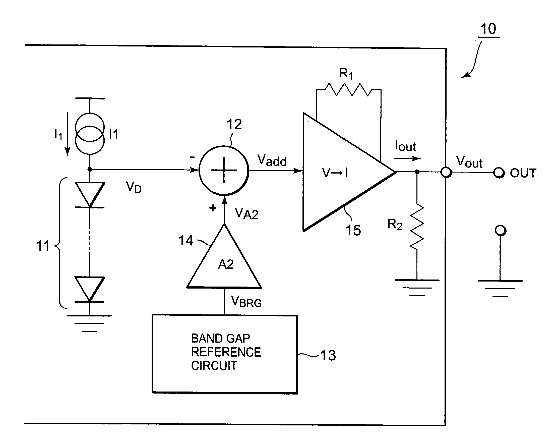
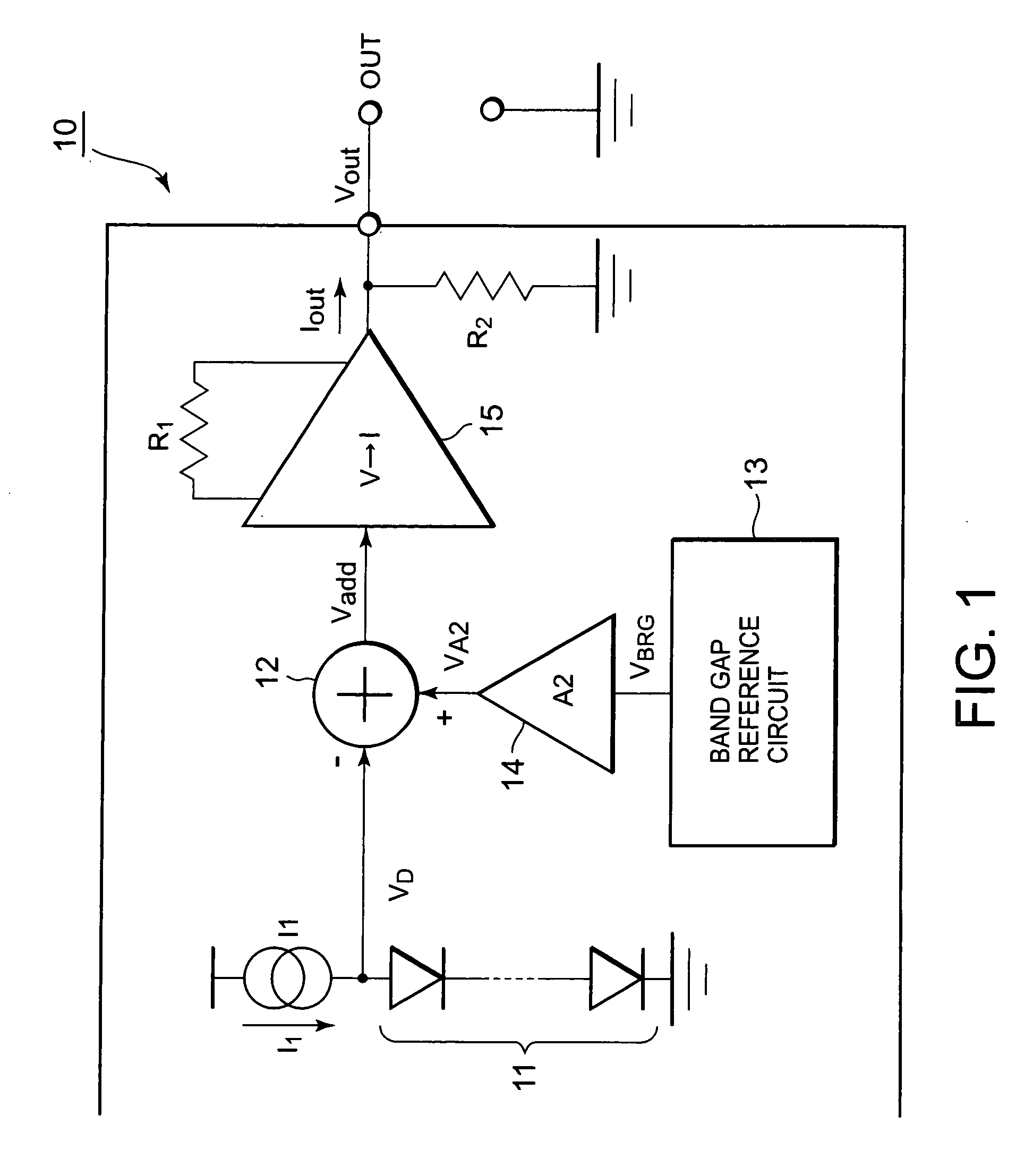
[0056]FIG. 1 is a block diagram showing a temperature detection circuit according to the first embodiment of the present invention. As shown in FIG. 1, a temperature detection circuit 10 comprises a group of diodes 11 consisting of one or more diodes connected in series, a constant current source I1 connected to the group of diodes 11, and an output unit for outputting the voltage or the current according to the detection temperature based on the voltage difference between a comparison voltage and a reference voltage generated by the group of diodes 11.

[0057]The output unit according to the present embodiment is configured by an adder 12, a voltage current converter 15, and a resistor R2 as a second resistor, and outputs a voltage VOUT according to the detection temperature. The temperature detection circuit 10 further comprises a BGR circuit 13 for generating a band gap reference voltage (BGR voltage) and an amplifier 14 for amplifying the BGR voltage, and inputs the voltage having...

second embodiment

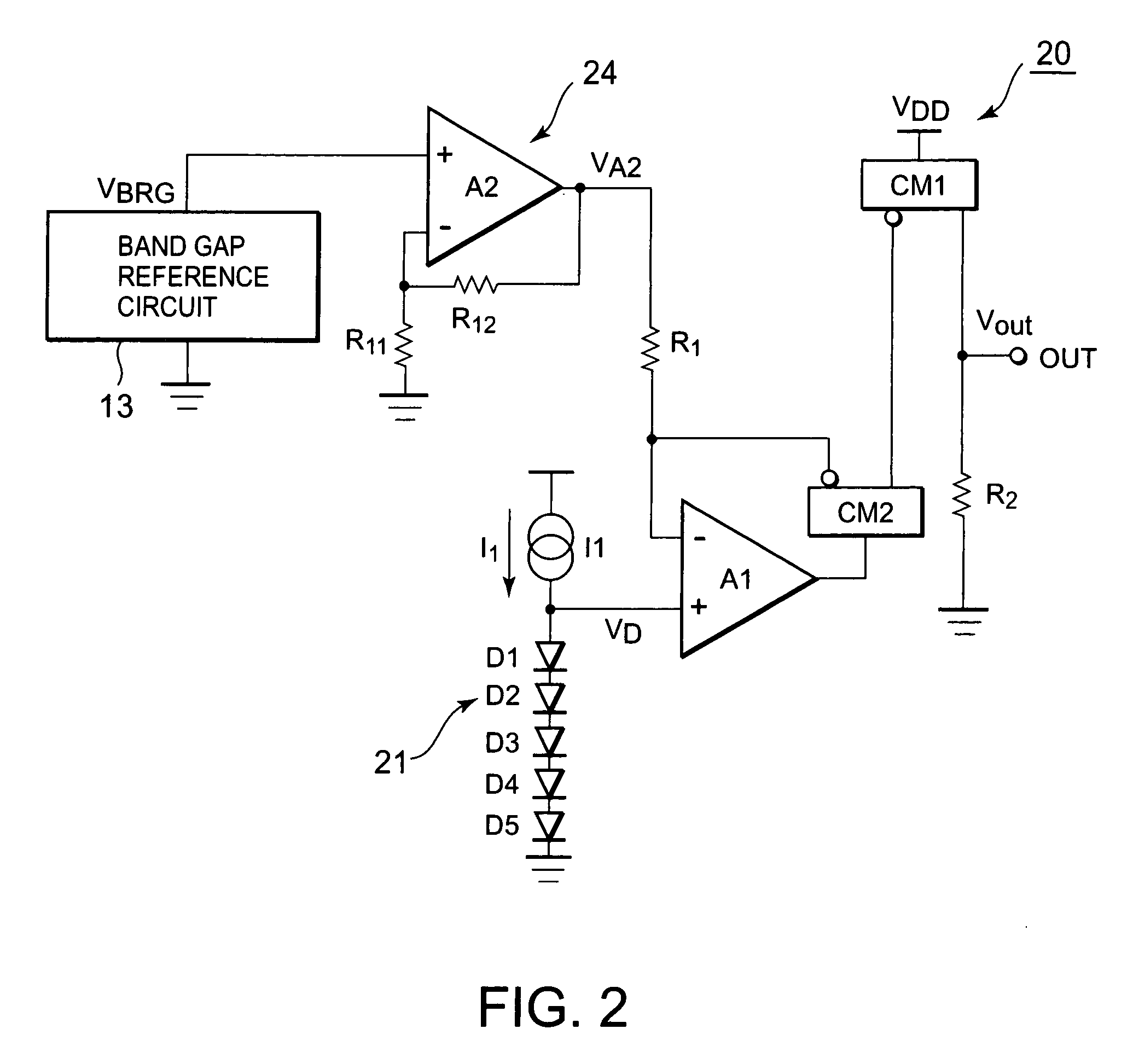
[0083]Next, a second embodiment of the present invention will be described. A temperature detection circuit according to the present invention is such that, when offset voltages of the first and second operational amplifiers A1 and A2 cause a problem, for example, for the temperature detection circuit 20 shown in FIG. 2, measures are taken to meet the problem. FIG. 6 is a view showing a temperature detection circuit according to the present embodiment. Incidentally, in the temperature detection circuit according to the present embodiment shown in FIG. 6, the same component parts as the temperature detection circuit shown in FIG. 2 are attached with the same reference numerals, and the detailed description thereof will be omitted.

[0084]As shown in FIG. 6, a temperature detection circuit 40 according to the present embodiment takes the first and second operational amplifiers A1 and A2 shown in FIG. 2 as operational amplifiers A11 and A12 attached with an offset cancellation circuit, a...

third embodiment

[0104]Next, a third embodiment of the present invention will be described. FIG. 10 is a block diagram showing a temperature detection circuit according to the present embodiment. As shown in FIG. 10, a temperature detection circuit 60 according to the present embodiment is provided with an amplifier 65 in place of the amplifier 14 and the resistor R2 in the temperature detection circuit 10 shown in FIG. 1. Similarly to the first embodiment, the series voltage (comparison voltage) VD of a group of diodes 11 plurally connected in series biased by a constant current source I1 is minus added by an adder 12, and a voltage (reference voltage) VA2 amplifying a BGR voltage VBGR by the amplifier 14 is plus added. The output voltage of this adder 12 is amplified by an amplifier 65, and the amplified voltage is outputted from the output terminal OUT serving as the output terminal of the temperature detection circuit 60.

[0105]Next, the operation of the temperature detection circuit according to...


PUM

PropertyMeasurementUnit
temperatureaaaaaaaaaa

Abstract

To provide a temperature detection circuit and a semiconductor device capable of accurately detecting temperatures. A temperature detection circuit 10 includes a group of diodes 11 connected in series, a constant current source I1 connected to the group of diodes 11, a BGR circuit 13, an amplifier 14 for amplifying the BGR voltage, an adder 12 for subtracting a comparison voltage VD generated by the group of diodes 11 from a reference voltage serving as an output of the amplifier 14, a voltage current converter 15 for converting the output voltage of the adder 12 into the current, and a resistor R2 for converting its output current into the voltage. The reference voltage VA2 is a BGR voltage VBGR amplified by the same voltage as the comparison voltage VD at a predetermined temperature T1.

Description

BACKGROUND OF THE INVENTION[0001]1. Field of the Invention[0002]The present invention relates to a temperature detection circuit, in particular, a temperature detection circuit which outputs a voltage or a current proportional to a chip temperature when a power consumption in a chip such as a power IC is on a high level and the chip temperature is required to be detected, and a semiconductor device mounting this temperature detection circuit.[0003]2. Description of Related Art[0004]In recent years, in general, the integration of LSI has been advanced, and many of circuits are being mounted within one chip. Power consumption is increased in proportion to a scale of the circuit. Alternatively, even when many of circuits are not mounted, a circuit such as a power IC consumes inherently high power. In such a case, the chip temperature rises, and in the worst case, the chip is likely broken down. To avoid this, it is demand to detect the chip temperature of the semiconductor device and c...

Claims


Application Information

Patent Timeline
Patent Type & Authority Applications(United States)
IPC IPC(8): G01K7/01G01K7/00
CPCG01K7/015
Inventor NISHIMURA, KOUICHI
Owner RENESAS ELECTRONICS CORP
Why Eureka
Try Eureka