Deck mounted pull riser tensioning system

a technology of tensioning system and riser, which is applied in the direction of drilling pipes, vessel construction, transportation and packaging, etc., can solve the problems of frequent maintenance of tensioner units, and achieve the effect of reducing the overall footprint of the system

Inactive Publication Date: 2008-02-07
WYBRO PIETER G +1
View PDF2 Cites 42 Cited by
  • Summary
  • Abstract
  • Description
  • Claims
  • Application Information

AI Technical Summary

Benefits of technology

[0019] One of the advantages of the present system is that the tensioner cylinder arrangement uses multiple, direct acting cylinders configured in a manner to minimize the overall footprint of the system and to achieve maximum tensioner stroke with minimum overall length of the cylinders.
[0020] Another advantage of the present system is that the tensioner cylinder configuration incorporates an accumulator system to achieve a desired stiffness variation with cylinder stroke, and in applications where multiple riser tensioning systems are deployed on the platform or vessel, the accumulator system may be shared between tensioner cylinders.
[0021] Another feature and advantage of the present system is that the rods of the tensioner cylinders are connected to a common load structure member that in turn supports a riser attachment which is attached to the riser itself and allows the attachment to the riser be variably adjusted vertically thereon to accommodate variations in the riser stack-up relative to the seafloor.
[0022] Another feature and advantage of the present system is that the interface between the riser and the load structure member may be rigidly fixed, or supported by a spherical bearing connection to offer a degree of relative rotational freedom.

Problems solved by technology

Typically these types of tensioner units require frequent maintenance due to the constant motion producing wear and degradation of the wire rope members and occupy a relatively large space on the supporting structure.

Method used


Image

  • Deck mounted pull riser tensioning system
  • Deck mounted pull riser tensioning system
  • Deck mounted pull riser tensioning system

Examples


Embodiment Construction

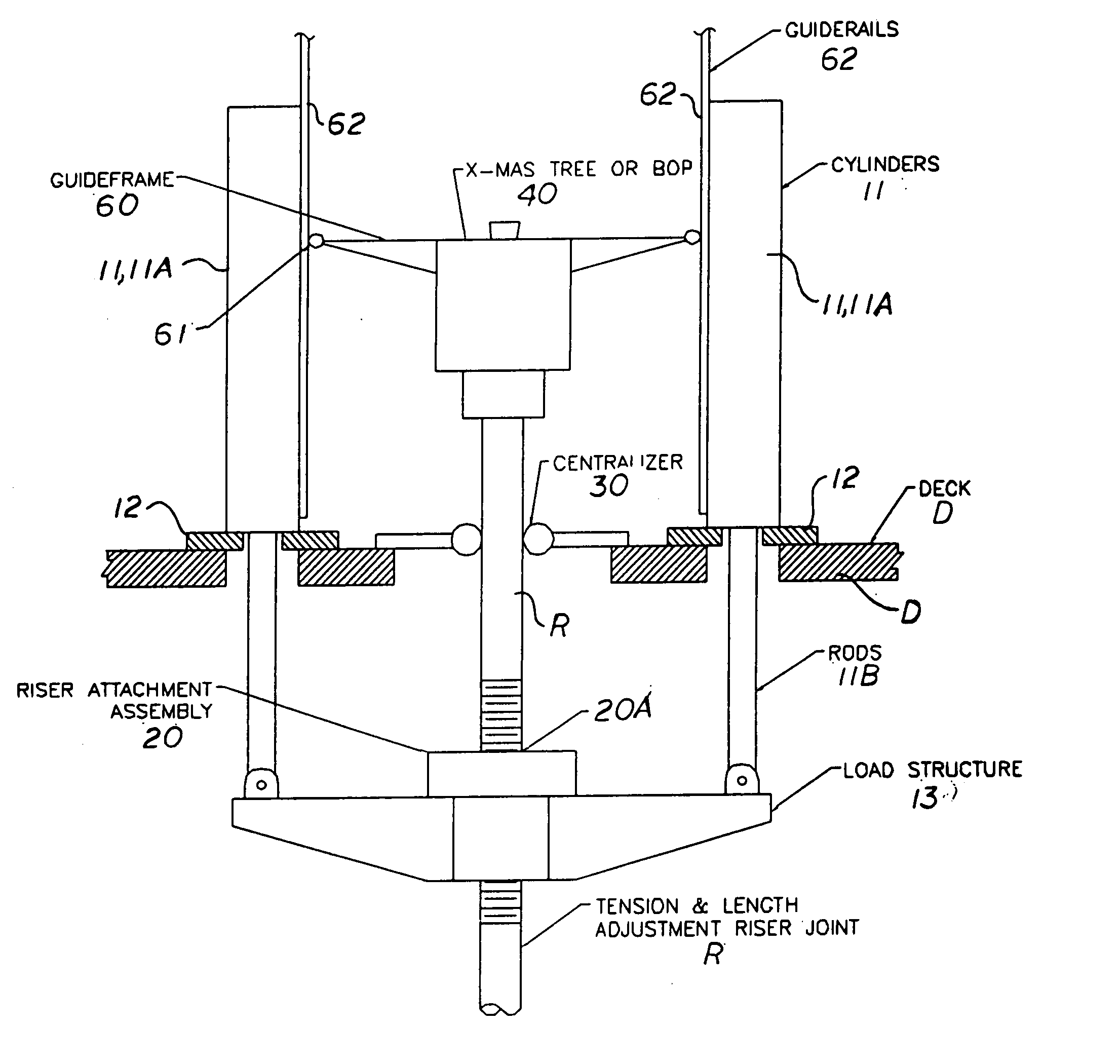
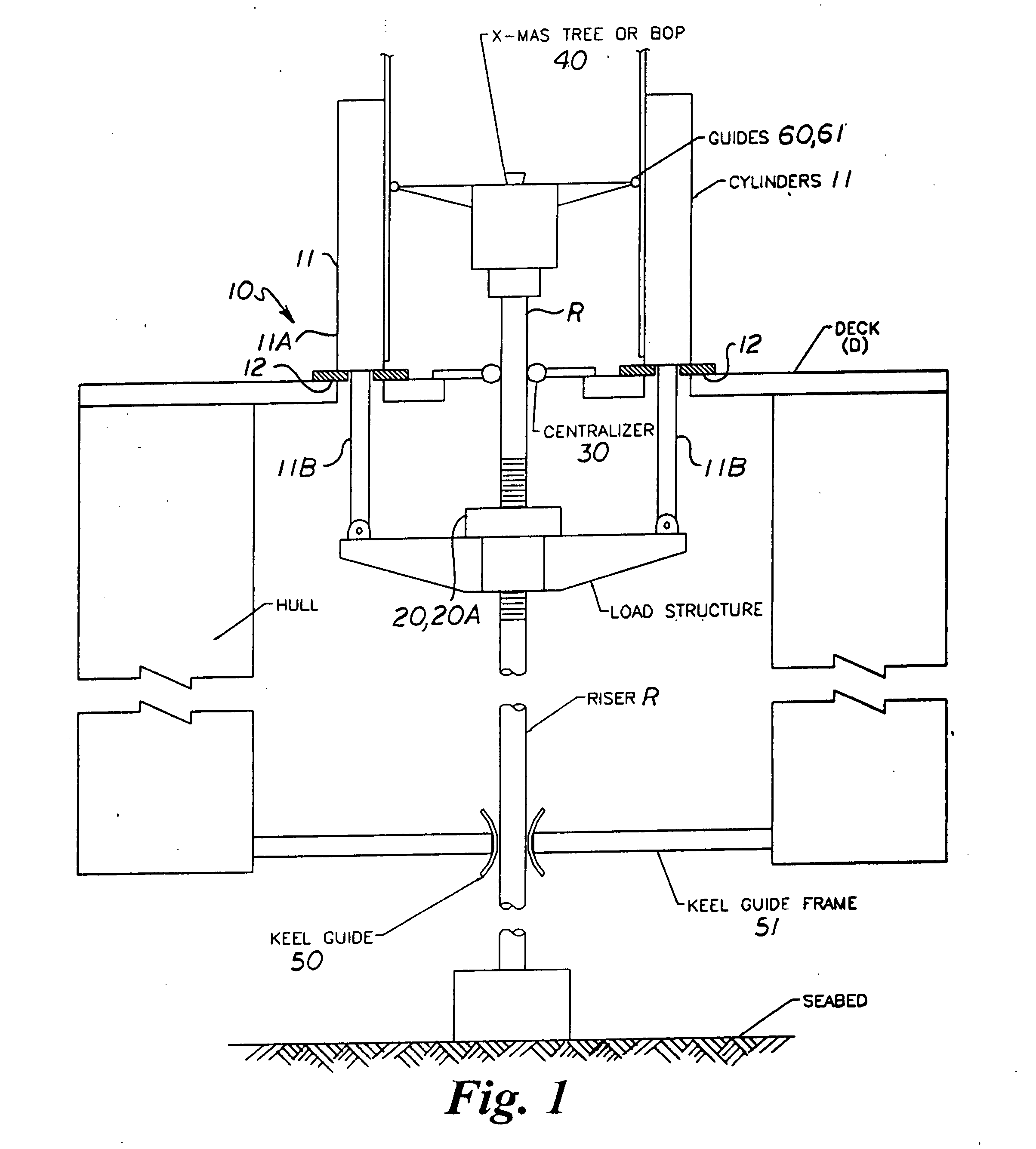
[0038] Several preferred embodiments of the present deck mounted riser tensioning system are described herein for use in tensioning a riser connected with a floating oil and gas drilling and / or production platform or vessel. As described hereinafter, the riser tensioning system utilizes multiple (at least two), direct acting tensioner cylinders configured in a manner to minimize the overall footprint of the tensioner system and to achieve maximum tensioner stroke with minimum overall length of the cylinders. Several preferred embodiments are described below wherein the tensioner cylinders are disposed in a vertical, a near vertical, or a vertically offset orientation, and supported at a lower deck level or upper deck level of the platform or vessel and may be rigidly fixed to the supporting deck or supported by various bearing supports to substantially prevent or to allow relative rotational movement between the cylinders and the deck on which they are supported.

[0039] In the follo...


PUM


Abstract

A deck mounted pull riser tensioning system for a floating platform or vessel includes at least two cylinders having a cylinder body supported at an upper or lower end on a deck or tensioner support structure of the platform or vessel in spaced apart relation with the cylinder rods extending downwardly from the cylinder body, or vice versa. A load structure member is connected to lower ends of the cylinder rods or bodies and has an opening therethrough for receiving a portion of a riser extending from the seafloor. A vertically adjustable riser attachment supported on the load structure member over the opening attaches to a portion of the riser extending through the opening and generally centrally between the cylinders. The cylinders pull upwardly on the load structure member to exert an upward tensioning force on the riser at the location of the riser attachment.

Description

CROSS REFERENCE TO RELATED APPLICATION [0001] This application claims priority of U.S. Provisional Patent Application Ser. No. 60 / 835,655, filed Aug. 3, 2006.BACKGROUND OF THE INVENTION [0002] 1. Field Of The Invention [0003] This invention relates generally to riser tensioner systems for offshore floating platforms and vessels, and more particularly to a deck mounted pull riser tensioning system for use on floating platforms and vessels that incorporates direct acting cylinders having cylinder rods connected with a load structure member that has a riser attachment which attaches to a riser extending therethrough and generally centrally between the cylinders whereby the cylinders exert an upward tensioning force on the riser. [0004] 2. Background Art [0005] Marine riser systems are employed to provide a conduit from a floating platform or vessel at the water surface to the blowout preventer stack or, production tree, which is connected to the wellhead at the sea floor. A tensioning ...

Claims


Application Information

Patent Timeline
Patent Type & Authority Applications(United States)
IPC IPC(8): B63B21/50
CPCE21B19/002B63B21/502B63B1/107B63B2001/128
Inventor WYBRO, PIETER G.KIPP, ROBERT M.
Owner WYBRO PIETER G
Why Eureka
Try Eureka