Jet pump slip joint with axial grooves

Inactive Publication Date: 2008-02-07
TORRES MARTIN R
View PDF10 Cites 28 Cited by
  • Summary
  • Abstract
  • Description
  • Claims
  • Application Information

AI Technical Summary

Benefits of technology

[0020]Further, in known slip joint structures, both the total leakage flow and the leakage flow around the annulus and within the slip joint varied depending on the relative position of the mating parts. Non-uniform slip joint leakage flow, in both the total flow and peripheral flow, incurred time-varying lateral forces on the mating parts of the slip joint. These time-varying lateral forces incurred relative motion of the mating parts. This relative motion lead to increased non-uniform flow and higher fluid forces that, in turn lead to higher levels of vibration and wear of the mating jet pump components. This spiraling condition lead to higher and higher vibration levels of the mating parts. The axial grooves of the present invention impose uniform leakage flow at the slip joint location. The imposed uniform leakage flow does not change in its total amount, nor periphery within the slip joint annulus due to relative motion of the slip joint mating parts. The uniform leakage

Problems solved by technology

Recent engineering experience has shown that if a sufficient pressure gradient exists across these slip joint interfaces, the connecting tubular components may incur detrimental flow-induced vibration, and failure results from either excessive wear or fatigue of the piping material or support/restraining apparatus.
Excessive leakage flow, however, can cause oscillation motion in the slip joint, which is a source of detrimental vibration excitation in the jet pump assembly.
Additional detrimental conditions that may lead to damaging vibration between the inlet mixer and diffuser of the jet pump assembly are well-known, such as loss of the set screw support in a jet pump assembly as described in U.S. Pat. No. 6,394,765 to Erbes, et al.
The resultant increased vibration levels and corresponding vibration loads on the piping and su

Method used


Image

  • Jet pump slip joint with axial grooves
  • Jet pump slip joint with axial grooves
  • Jet pump slip joint with axial grooves

Examples


Embodiment Construction

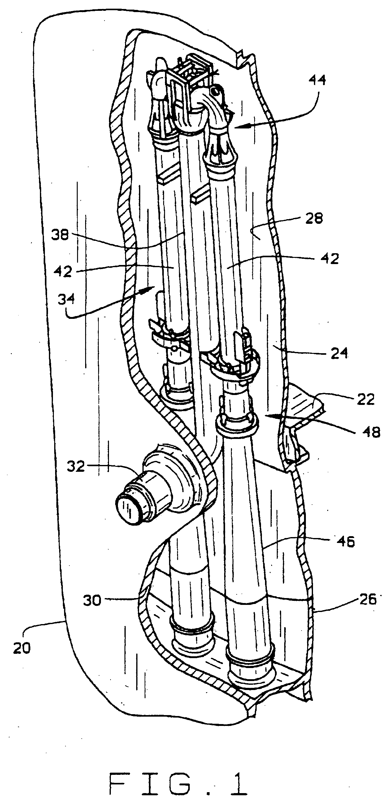
[0029]FIG. 1 is a schematic illustration of a portion of a conventional reactor pressure vessel (RPV) 20 for a boiling water reactor. Such reactors are previously described in U.S. Pat. No. 4,675,149 and U.S. Pat. No. 6,587,535, the disclosures of which are incorporated herein. The RPV 20 has a generally cylindrical shape and is closed at one end by a bottom head (not shown) and at its other end by removable top head (not shown). A top guide (not shown) is spaced above a core plate 22 within RPV 20. A shroud 24 surrounds the core plate 22 and is supported by a shroud support structure 26. An annulus 28 is formed between the shroud 24 and sidewall 30 of the RPV 20.

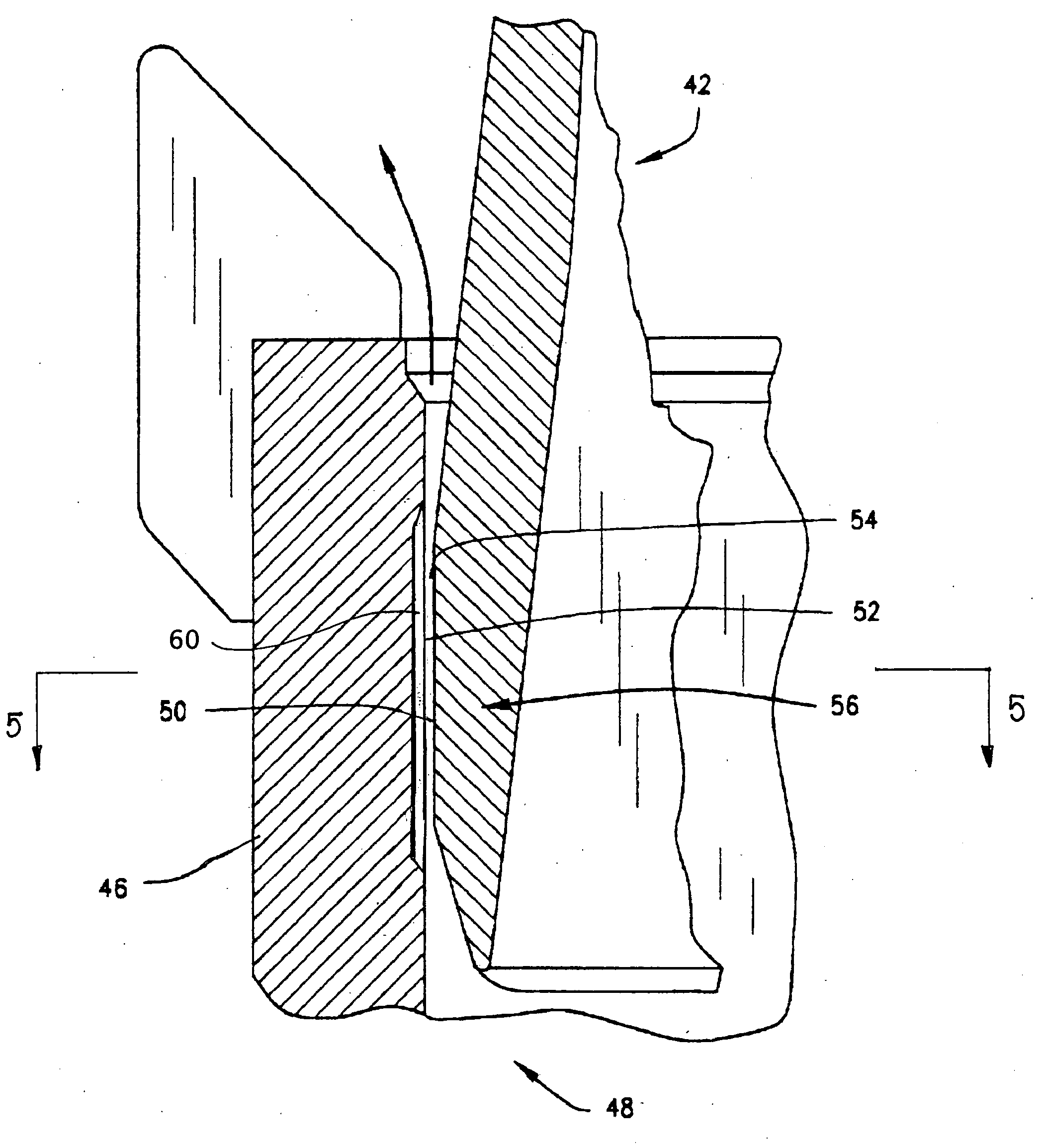
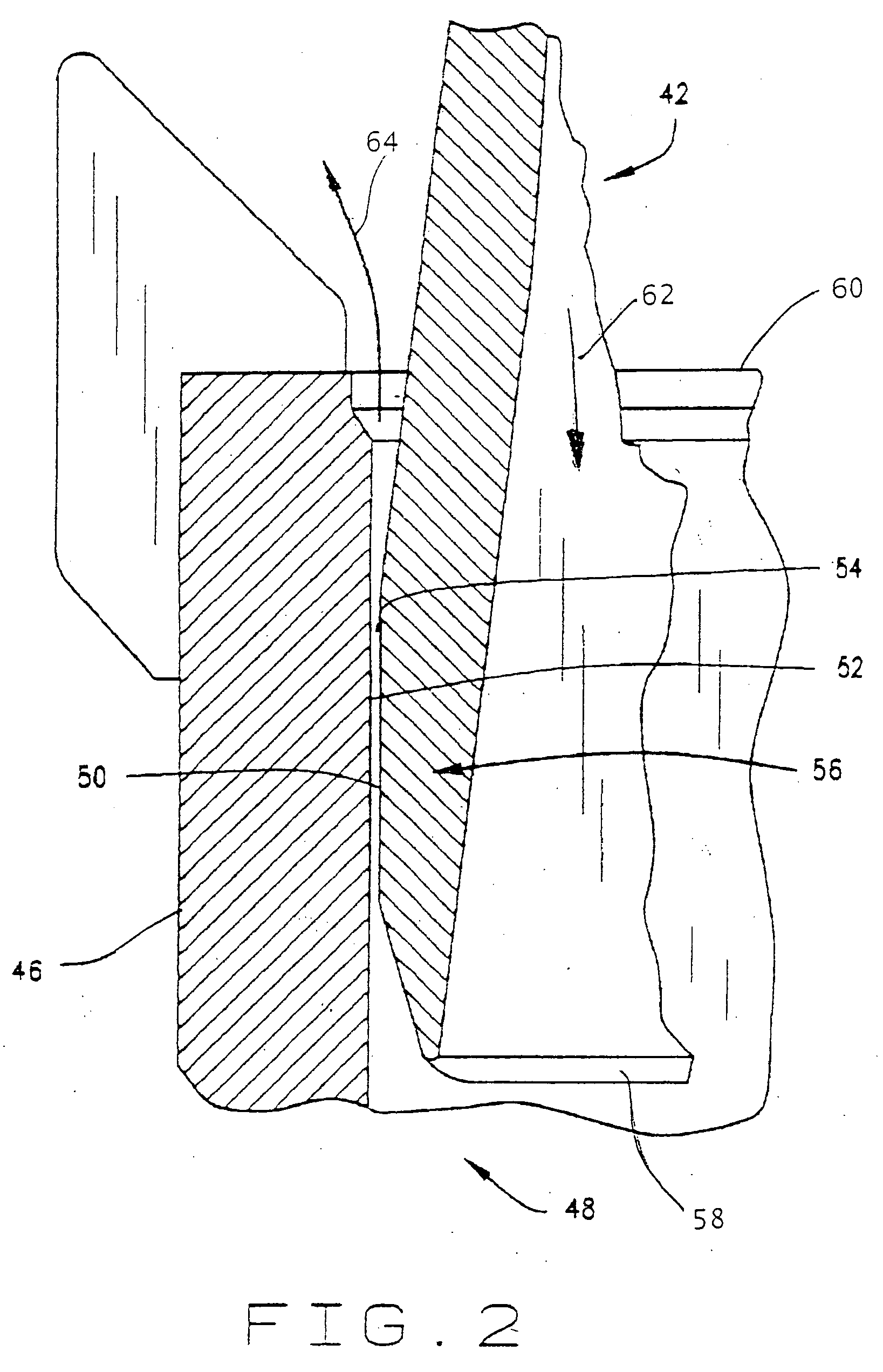
[0030]An inlet nozzle 32 extends through the sidewall 30 of the RPV 20 and is coupled to a jet pump assembly 34. The jet pump assembly 34 includes a riser pipe 38 and a plurality of inlet mixers 42 connected to the riser pipe 38 by a transition assembly 44. A diffuser 46 is connected to and positioned below each of the inle...


PUM


Abstract

A uniform leakage flow device for the slip point of piping systems, and particularly in reactor pressure vessels, selectively imposes a steady, uniform flow of fluid through the slip joint between two adjacent pipe surfaces to thereby eliminate the detrimental flow-induced vibration associated with the unsteady and non-uniform leakage of fluid through the slip joint field. The uniform leakage flow device comprises a plurality of axial grooves that are formed in the wall surface of the slip joint.

Description

CROSS-REFERENCE TO RELATED APPLICATION [0001]This application is a non-provisional application claiming priority to provisional patent application Ser. No. 60 / 834,929 filed Aug. 2, 2006.BACKGROUND OF THE INVENTION[0002]1. Field of the Invention[0003]This invention relates generally to tubular jet pumps used in various industries to transport and / or circulate cooling liquid in heat-generating systems, such as nuclear reactors and hydroelectric generation systems. More particularly, this invention relates to means for uniformly controlling the leakage flow rate through a slip joint to thereby eliminate detrimental vibration in the slip joints of such jet pumps.[0004]2. Description of Related Art[0005]Pipes, tubes and cylinders are used to transport a variety of fluids, such as water, oil, and liquid chemicals in various industries including the nuclear industry, the electric power industry, such as for internal components of heat exchangers, the hydroelectric power generation industry...

Claims


Application Information

Patent Timeline
IPC IPC(8): F04F5/00
CPCF04F5/464F04F5/46
Inventor TORRES, MARTIN R.
Owner TORRES MARTIN R
Why Eureka
Try Eureka