
Golf Swing Plane Training Device And Method

Inactive Publication Date: 2008-02-07
MCFARLIN JAMES A +1
View PDF16 Cites 4 Cited by
  • Summary
  • Abstract
  • Description
  • Claims
  • Application Information

AI Technical Summary

Benefits of technology

[0012]The present invention relates to a golf swing plane training device that also serves as an exercising device to help the user develop the muscle memory of swinging on plane as well as exercise the muscle groups most effective in imparting maximum power to a golf ball. The device is portable and comprises a rotating swing plane guide, one end pivotably connected to a golf club shaft, for constraining and controlling the swing arc of the golf club shaft when swung by the user to ingrain the feel of swinging on plane and consequently develop a correct golf swing. The other end of the rotating swing plane guide is connected to a rotation control assembly. A resistance source is connected to the hub of the rotation control assembly to provide resistance force against the club shaft on the downswing, strengthening the muscle groups that need be activated to maximize power and intensifying the proper feel of a correct swing.
[0013]One object of the present invention provides a golf swing plane training device that is relatively compact is size and is realistically portable. The device is collapsible; it can be set up at a suitable location for a practice session, and then folded into a storage configuration.
[0014]Another object of the present invention provides a golf swing plane training device that includes a rotation control assembly mounted on a vertically adjustable support frame. The rotation control assembly is set at an angle that is adjustable, but fixed during operation. This angle determines the axis of rotation and, thus, the angle of the swing plane. The adjustability of the height of the device and the plane angle allows the device to be used by all golfers.
[0015]A further object of the present invention provides a golf swing plane training device having a swing plane guide which comprises a rotatable, largely concave swing arm to constrain and restrict the club shaft from moving down on a swing plane steeper than that of the backswing. The curved shape of the swing plane guide allows it to clear the user's head when the swing is approaching the top of the swing or the end of the follow-through. The swing plane guide further comprises a radius adjustment assembly, connected to the swing arm, which includes a linear track having an axis perpendicular to the swing plane axis of rotation. A universal pivoting assembly is employed to connect a golf club shaft to the swing arm via a carriage slidably disposed on the linear track. Thus, the golf club shaft is not connected to the swing plane guide at a fixed point, which would force the golf club shaft to follow a circular swing arc. The connecting point is at the carriage which is free to slide along the linear track, and the golf club shaft can follow a swing arc that flattens toward the top of the swing.
[0016]Still a further object of the present invention provides a golf swing plane training device that employs a universal joint for connecting the golf club shaft to the swing plane guide, allowing the club shaft to pivot freely relative to the swing plane guide and to slide within the universal joint. Hence, the swing arc is not limited to strictly follow a circular shape, and the swing arc can be extended on the backswing and narrowed on the downswing by varying degrees as is natural to different golfers. Furthermore, the radius adjustment assembly includes a swing plane varying assembly which extends and retracts axially, allowing the user to initiate the downswing on a slightly flatter swing plane.
[0017]Yet one further object of the present invention provides a golf swing plane training device that contains a resistance source for exercising the muscle groups which are most effective in transferring maximum power to a golf ball. The resistance force preferably is only engaged on the downswing and is disengaged on the backswing, as the goal during the backswing is to achieve smooth motion and full extension in order to maximize leverage.

Problems solved by technology

Of all the elements, the concept of the swing plane may possibly be the most complicated to grasp.
However, many golfers do not have a clear understanding of what the swing plane is and what it is that should be on this plane.
Furthermore, other referential concepts intended to help golfers gain understanding may be misinterpreted by some.
Conceptual planes like these serve as valuable checkpoints of a golfer's swing at discrete steps; however, they do not describe the plane the club travels on throughout a golf swing.
For a normal golf shot, when the golfer is not attempting to shape the ball flight, the downswing should not be on a steeper plane than that of the backswing, which tends to lead to the dreaded “outside-in” move not conducive to a good golf shot.
Finally, there is not a singular “ideal” swing plane that is suitable for all golfers.
Even with a sound understanding of the concept, it is difficult for a golfer to work on his / her swing plane without the assistance of an instructor or a training device.
Also, the flexible cord exerts little control over the path of the movement of hands or the swing plane.
That is to say, most of these devices do not take into account the perfectly allowable variations in golfers' swings.
Also, these devices are outsized, difficult to transport, and tend to be expensive to manufacture.
his forces some golfers to unnecessarily alter their swing. (
o means is provided to adjust the angle of the swing plane. (
5) Dissimilar shapes are involved where the club shaft is attached to the rotating rod, creating friction and hampering smooth motion transmission. F
6) The device does not allow the user to make a full swing as the rod would not clear his / her head. (
7) The device is too complicated or too expensive to manufacture to be economically viable. (
8) The device is outsized or requires being anchored on an opposing wall, thus is not transportable.

Method used


Image

  • Golf Swing Plane Training Device And Method
  • Golf Swing Plane Training Device And Method
  • Golf Swing Plane Training Device And Method

Examples


Embodiment Construction

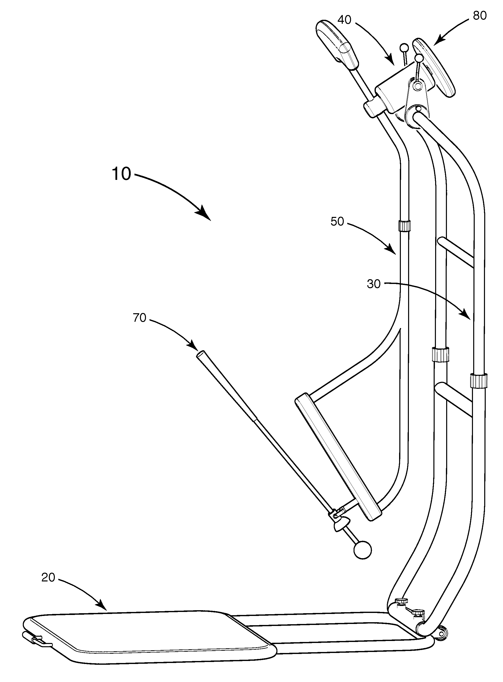
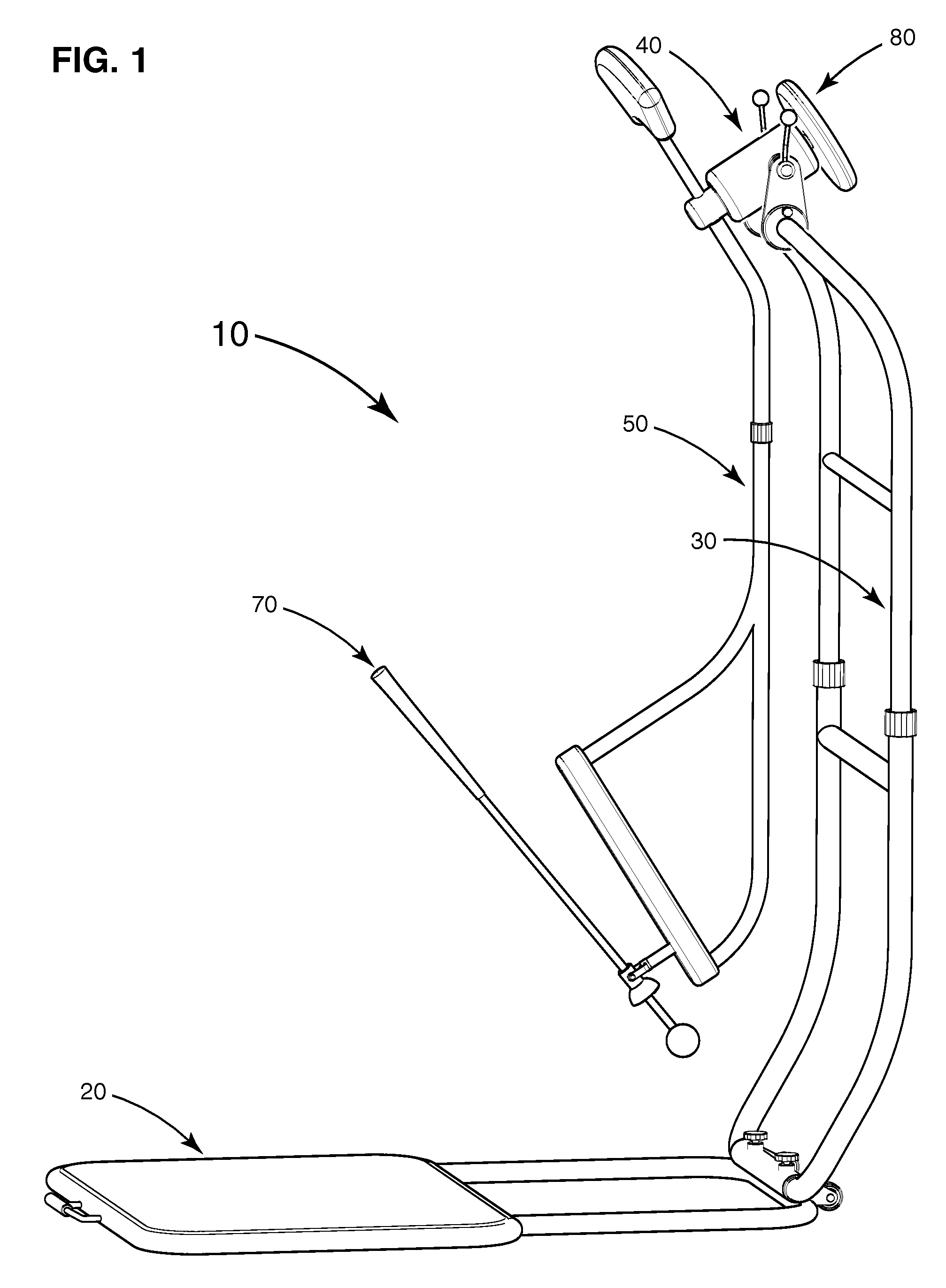
[0029]The golf swing plane training device according to the concepts of the present invention and how it functions can best be explained by reference to the attached drawings. As illustrated in FIG. 1, the preferred embodiment of the golf swing plane training device 10 comprises a base member 20, a support frame 30, a rotation control assembly 40, a swing plane guide 50, a simulated golf club 70, and a resistance mechanism 80.

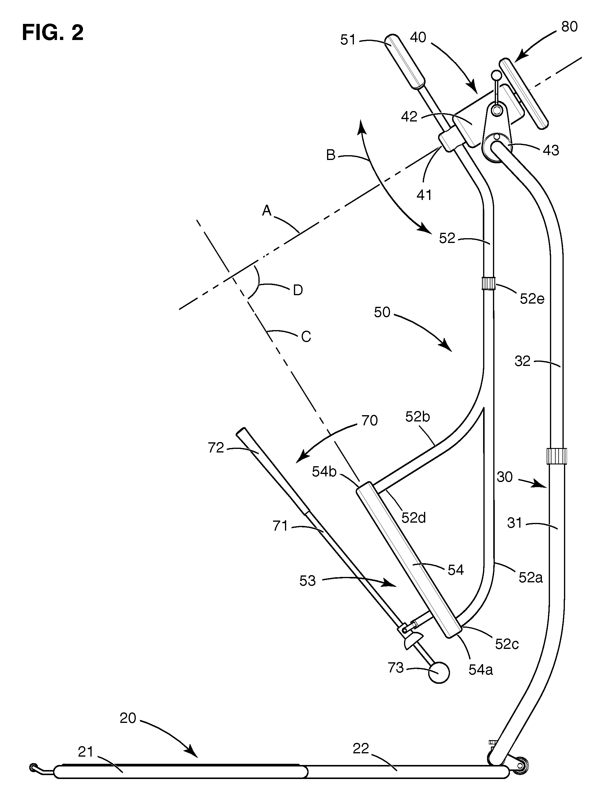
[0030]Referring now to FIG. 2, the base member 20 consists of a base platform 21 that is generally rectangular in shape for supporting and positioning the user by standing on it. The weight of the user standing on the base platform 21 serves to stabilize the device. The upright support frame 30 consists of a lower support portion 31 and an upper support portion 32. The upper support portion 32 is vertically adjustable such that the height of the device can be altered to suit the user's stature. The adjustment can be implemented using any conventional means suit...


PUM


Abstract

A golf swing plane training device is disclosed that helps the user develop a correct swing plane as well as exercise the muscle groups most effective in imparting maximum power to a golf ball. The device is portable and comprises a rotating swing plane guide, one end pivotably connected to a club shaft, for controlling the swing arc of the club shaft when swung by the user to ingrain the feel of swinging on plane. The other end of the rotating swing plane guide is connected to a rotation control assembly mounted on a vertically adjustable support frame. A resistance source is connected to the hub of the rotation control assembly.

Description

RELATED APPLICATIONS[0001]This is a utility patent application filed under 35 U.S.C. 111(a) and claiming the benefit under 35 U.S.C. 119(e)(1) of the filing date of provisional application Ser. No. 60 / 835,791 filed on Aug. 4, 2006BACKGROUND OF THE INVENTION[0002]1. Field of the Invention[0003]The present invention relates in general to a golf swing plane training device, and more particularly to a golf swing plane training device that comprises a rotating swing plane guide, one end pivotably connected to a golf club shaft, for constraining and controlling the swing arc of the golf club shaft when swung by a golfer to ingrain the feel of swinging on plane and consequently develop a correct golf swing.[0004]2. General Background[0005]Golf is a sport that has a centuries-long history and has been studied exhaustively by devoted golfers in their quest to understand and master the fundamentals of the golf swing mechanics. There is a constant stream of instructions in the form of books, v...

Claims


Application Information

Patent Timeline
IPC IPC(8): A63B69/36
CPCA63B21/157A63B21/225A63B2225/093A63B2210/50A63B2225/09A63B69/365A63B69/36213
Inventor MCFARLIN, JAMES A.MCFARLIN, MARGARET
Owner MCFARLIN JAMES A
Learn More