Optical continuum source including light generation beyond wavelength edges of continuum

Active Publication Date: 2008-09-25
FURAKAWA ELECTRIC NORTH AMERICA INC
View PDF8 Cites 3 Cited by
  • Summary
  • Abstract
  • Description
  • Claims
  • Application Information

AI Technical Summary

Benefits of technology

[0012]Another aspect of the present invention is the ability to utilize “tunable” gratings (for example, thermal tuning or mechanical tuning) to adjust the wavelength(s) to completely phase match the nonl

Problems solved by technology

Previous efforts at continuum generation, typically performed using light pulses having durations on the order of picoseconds (10-12 sec) in kilometer lengths of fiber, have unfortunately shown degradation of coherence in the generation process.
In particular, additional noise has been found to be introduced into the system during the spectral broadening aspect of

Method used


Image

  • Optical continuum source including light generation beyond wavelength edges of continuum
  • Optical continuum source including light generation beyond wavelength edges of continuum
  • Optical continuum source including light generation beyond wavelength edges of continuum

Examples


Embodiment Construction

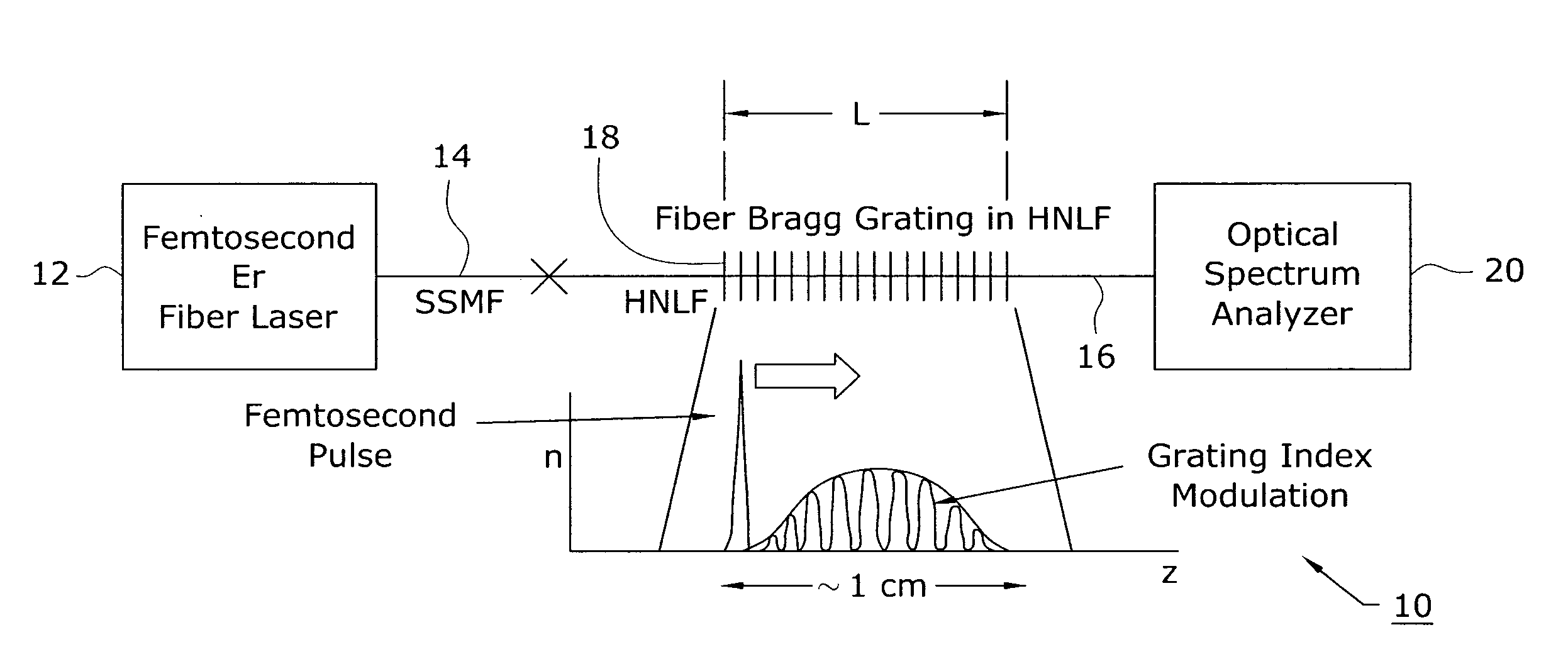
[0022]It has previously been shown that a fiber Bragg grating can greatly enhance continuum generation in nonlinear fibers, as disclosed in U.S. Pat. No. 7,116,874 issued to Brown et al. on Oct. 3, 2006. In the Brown et al. teaching, one or more Bragg gratings having a Bragg wavelength (resonant wavelength) within the bandwidth of the continuum were used to “enhance” the continuum in the local area of the Bragg wavelength. In the arrangement of Brown et al., the wavelength was selected to lie within the continuum, so that there was a sufficient amount of light energy present to allow for the enhancement to occur.

[0023]It has since been discovered that a Bragg grating having a resonant wavelength outside an existing continuum will still allow for a resonant peak to be generated. That is, it has been found that the generation of additional light by the incorporation of Bragg gratings within a section of HNLF used for continuum generation does not rely on the presence of any significan...


PUM


Abstract

An optical continuum source is formed that is used to generate both a continuum and one or more light peaks outside the bandwidth of the continuum. In particular, one or more fiber Bragg gratings exhibiting a resonant wavelength less than the short wavelength edge (or greater than the long wavelength edge) of a predetermined continuum are inscribed into a section of highly nonlinear fiber (HNLF) and used to generate the additional light peaks. Gratings may also be formed for areas along the fiber where the continuum spectral power density is essentially “zero”. It has been discovered that the use of a Bragg grating generates phase matching with the propagating optical signal, thus resulting in the creation of the additional peaks.

Description

TECHNICAL FIELD [0001]The present invention relates to a source for generating an optical continuum and, more particularly, to a source including the generation of one or more light peaks outside of the continuum, beyond its short wavelength and long wavelength edges.BACKGROUND OF THE INVENTION [0002]There are applications in the fiber optics field in which a high power, low noise, broadband light source is of particular interest. For example, efforts are now being made toward spectral slicing wherein a common light source is used to generate a multitude of wavelength division multiplexed (WDM) signals. Such an application thus has the potential for replacing many lasers with a single light source. Other applications include, but are not limited to, frequency metrology, device characterization, dispersion measurements made on specialty fibers, and the determination of transmission characteristics of gratings. All of these various diagnostic tools, as well as many other applications,...

Claims


Application Information

Patent Timeline
IPC IPC(8): H01S3/00
CPCG02F1/3544G02F2201/307G02F2001/3528G02F1/365G02F1/3528
Inventor NICHOLSON, JEFFREY W.WESTBROOK, PAUL S.
Owner FURAKAWA ELECTRIC NORTH AMERICA INC
Why Eureka
Try Eureka