Optical knife-edge detector with large dynamic range

Active Publication Date: 2016-08-18
TECHNION RES & DEV FOUND LTD
View PDF1 Cites 8 Cited by
  • Summary
  • Abstract
  • Description
  • Claims
  • Application Information

AI Technical Summary

Benefits of technology

[0019]A plurality of equally sized and equally spaced beams is impractical both from consideration of complexity and consideration of power efficiency. It is important to maximize the power illuminating the photoedetector pair for optimal performance. Therefore it would be preferable to incorporate the illumination power available into one beam and not split it between many such beams, which could result from dividing a single beam down into the separate beams. Consequently, according to a more practical second exemplary implementation, the effect of a plurality of equally spaced beams can be synthesized by use of a pair of reflecting surfaces, such as mirrors, disposed on either side of the single incident beam, and generally parallel to the common abutment edges of the photodetector element pair. The reflecting surfaces are aligned such that when looking down

Problems solved by technology

For very high sensitivities the alignment tolerance, or SDR, of the KET becomes impractical.
This limitation severely curtails the usefulness of the knife edge technique, despite its simplicity and high sensitivity.
Similarly, the SDR is also increased by a multiple of the number of bea

Method used


Image

  • Optical knife-edge detector with large dynamic range
  • Optical knife-edge detector with large dynamic range
  • Optical knife-edge detector with large dynamic range

Examples


Embodiment Construction

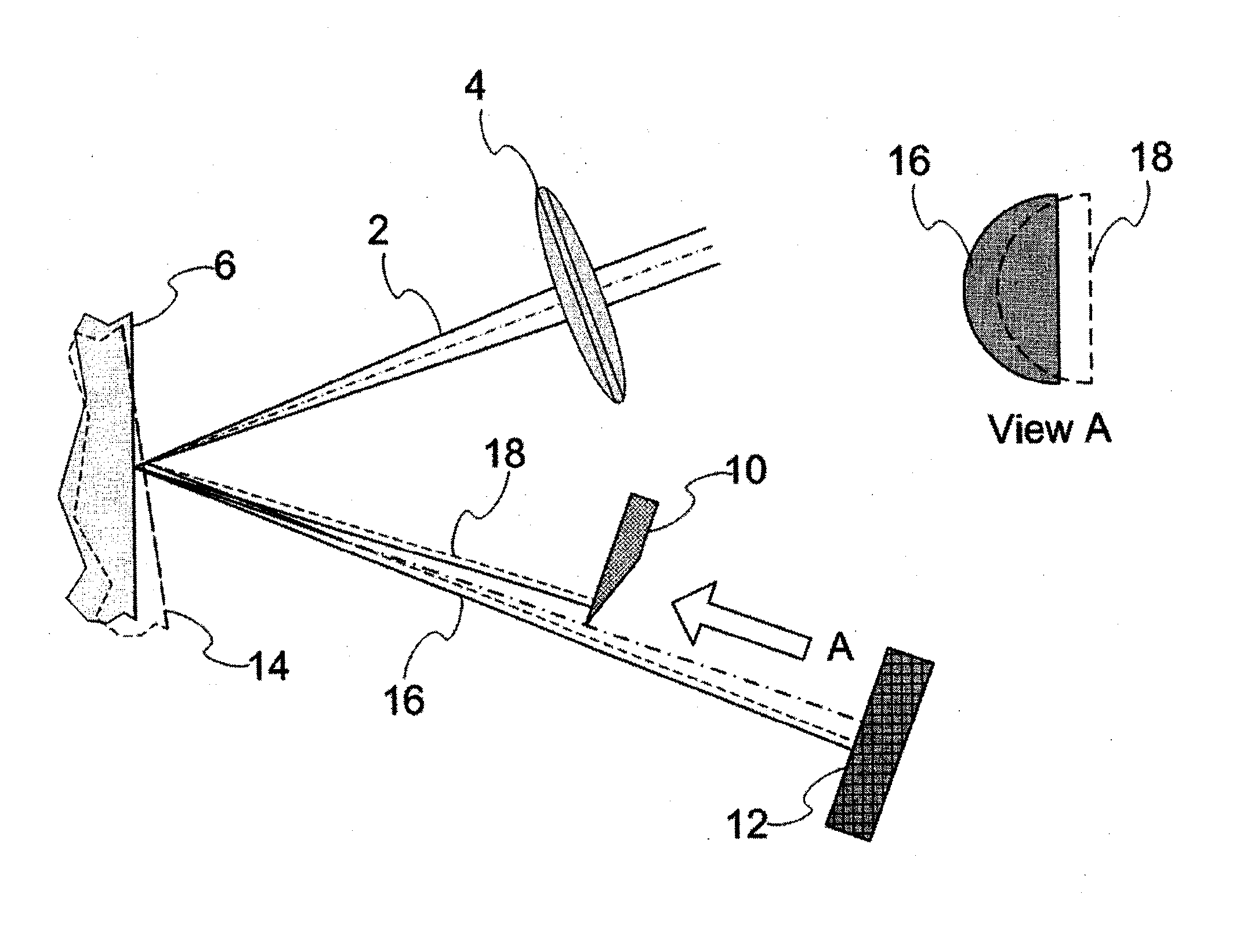
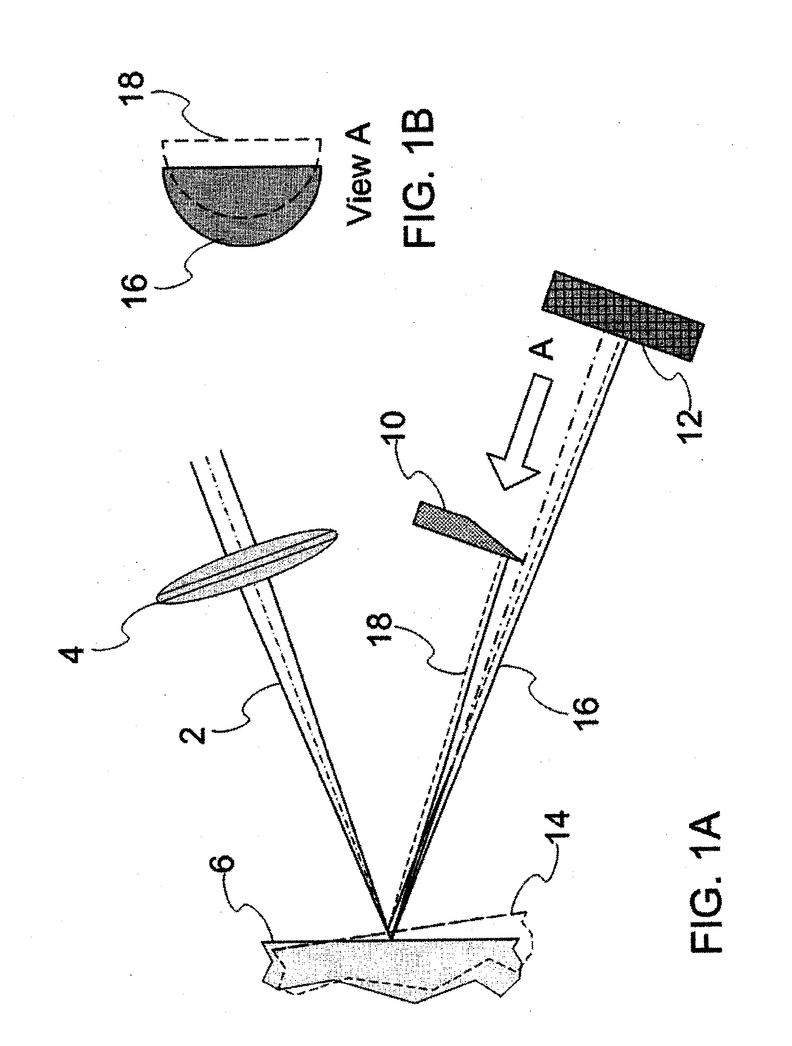
[0061]Reference is now made to FIG. 4, which illustrates schematically the physical basis of a method by which the setup sensitivity and dynamic ranges (SSR and SDR) of the split detector knife-edge technique (KET) can be substantially increased. In this implementation, instead of a single beam being used to traverse the split detector to provide displacement information for that single spot, an array of beams is generated from reflections off the optically monitored surface, which can be the surface being measured or the surface of a cantilever which moves in accordance with the surface being measured. As the spots from these beams traverse the detector in sequence, the amplifier output responds continuously to the position of the particular spot traversing the split detector. The SSR range is then increased in proportion to the number of beams in the train of beam spots used—the greater the number of spots, the greater the SSR. In order to provide continuous signal coverage, the s...


PUM


Abstract

A detection arrangement and method for directing the sensitivity of an optical knife-edge detection system to its optimal operating point. This is referred to as an increase in the detection dynamic range of the system with advantageous applications for detecting motion of a surface such as for Atomic Force Microscopy as well as detecting acoustic vibrations on unstable surfaces. A pair of parallel reflecting surfaces, such as an optical slab waveguide, serve to reflect the sensing beam back onto the knife-edge detector once it is shifted off its sensing range. Allowing multiple reflections, the sensing beam is maintained on the knife-edge detector even at large angular offsets from the optimal operating point of the basic knife-edge detector. Use of a modified arrangement, with two knife-edge detectors at quadrature ensures near-optimal sensitivity at a detection dynamic range up to forty-fold larger than that of the basic knife-edge system.

Description

FIELD OF THE INVENTION[0001]The present invention relates to the field of optical knife-edge detection of small perturbations, especially for use in nanometric monitoring systems, such as for use in ultrasensitive sensors or in atomic force microscopy applications.BACKGROUND OF THE INVENTION[0002]Originally introduced by August Toepler in 1864 to photograph fluids of varying densities, the knife-edge technique (KET), also referred to as Schlieren photography, was adapted in the middle of the 20th century for detection and visualization of ultrasound, such as in the article “An instrument for making surface waves visible” by R. Adler et al, IEEE Trans. Son. Ultrason. SU-15 p. 157, 1968. Since then, the KET has seen a variety of applications for detection of minute perturbations, including dynamic sensors for the detection of perturbation induced by acoustic waves, as in U.S. Pat. No. 7,957,006 to the present inventor, as well as sensors for detection of perturbations of scanning devi...

Claims


Application Information

Patent Timeline
IPC IPC(8): G01Q20/02G01J1/42
CPCG01Q20/02G01J1/4257G01H9/00G01D5/342
Inventor AHARONI, ABRAHAM
Owner TECHNION RES & DEV FOUND LTD
Why Eureka
Try Eureka