Methods for monitoring thermal ablation

a technology of thermal ablation and monitoring methods, applied in the field of thermal ablation systems and methods, can solve problems such as serious side effects and risks, tissue destruction, and tissue destruction

a technology of thermal ablation and monitoring methods, applied in the field of thermal ablation systems and methods, can solve problems such as serious side effects and risks, tissue destruction, and tissue destruction

US20080033418A1Inactive Publication Date: 2008-02-07ABLA TX +1

Image

  • Methods for monitoring thermal ablation
  • Methods for monitoring thermal ablation
  • Methods for monitoring thermal ablation

Examples


Embodiment Construction

[0117]In the following description, the invention is set forth in the context of apparatus and methods for planning, simulating and performing thermal ablation in a patient.

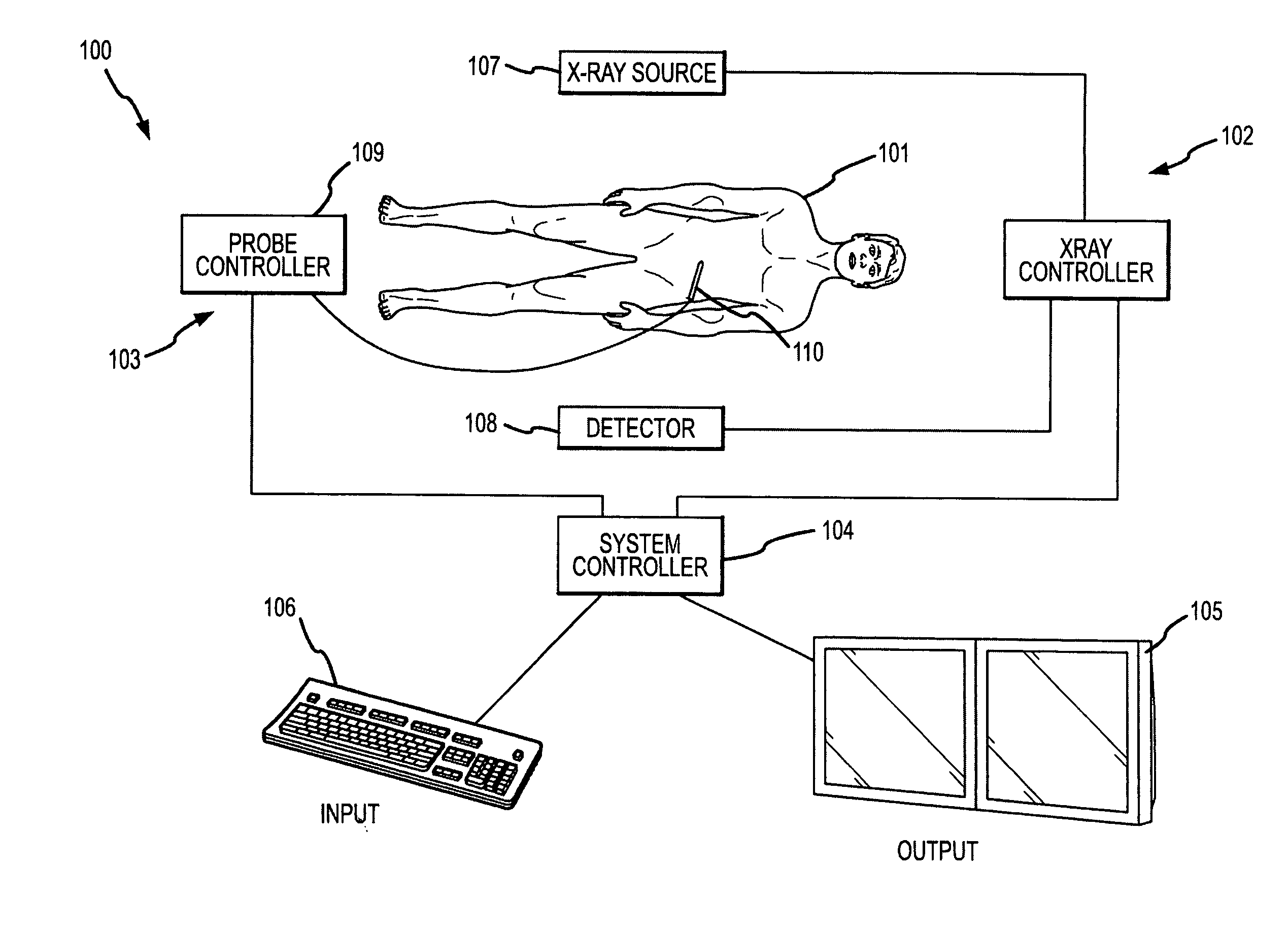
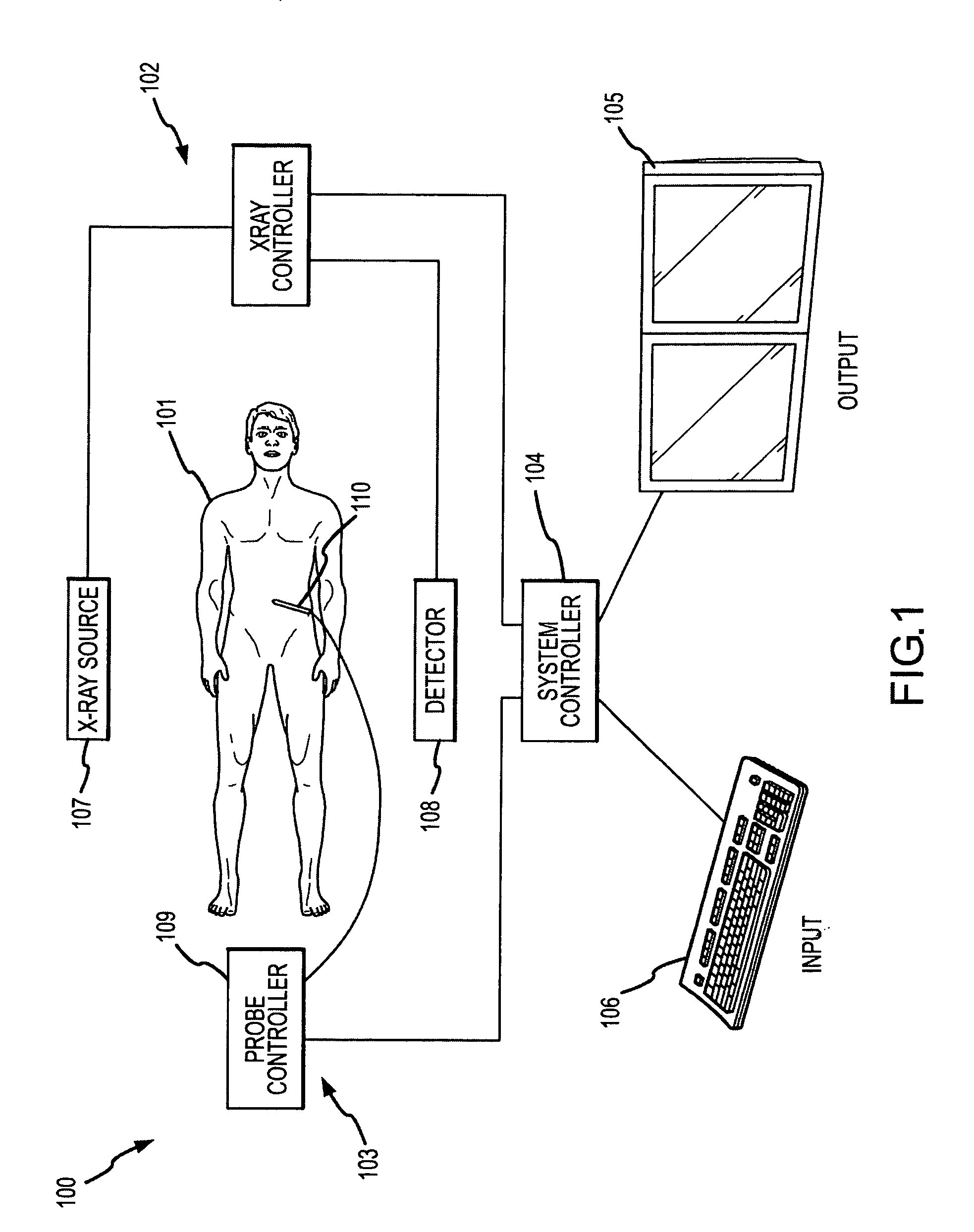
[0118]FIG. 1 illustrates, in schematic form, a thermal ablation apparatus 100 for performing thermal ablation on a patient 101. The illustrated components, each of which will be described in detail, are an x-ray imaging system 102, a thermal ablation delivery system 103 and a system controller 104. Interfaces for the thermal ablation apparatus 100 are represented schematically by an output device 105 and an input device 106.

[0119]The thermal ablation apparatus 100 is capable of performing a thermal ablation procedure within a Volume Of Interest (VOI) within a patient 101. During the procedure, the x-ray imaging system 102 may capture images of the VOI which may then be used by the system controller 104 to control the thermal ablation delivery system 103 to achieve the goals of a thermal ablation plan. The primary...


PUM


Abstract

A thermal ablation system is operable to perform thermal ablation using an x-ray system to measure temperature changes throughout a volume of interest in a patient. Image data sets captured by the x-ray system during a thermal ablation procedure provide temperature change information for the volume being subjected to the thermal ablation. Intermediate image data sets captured during the thermal ablation procedure may be fed into a system controller, which may modify or update a thermal ablation plan to achieve volume coagulation necrosis targets. The thermal ablation may be delivered by a variety of ablation modes including radiofrequency ablation, microwave therapy, high intensity focused ultrasound, laser ablation, and other interstitial heat delivery methods. Methods of performing thermal ablation using x-ray system temperature measurements as a feedback source are also provided.

Description

FIELD OF THE INVENTION[0001]The present invention relates to thermal ablation systems and methods and, in particular, to improved systems and methods for planning and performing thermal ablation.BACKGROUND OF THE INVENTION[0002]Thermal ablation involves the creation of temperature changes sufficient to produce coagulation necrosis in a specific volume of tissue within a patient, typically one or more benign and / or cancerous tumors. In the case of the application of temperatures elevated to above about 50 degrees C., the proper application of heat can result in tissue destruction primarily due to the destruction of proteins within the cells. In the case of reducing the temperature of the targeted area, cycles of proper freezing and thawing can result in tissue destruction primarily due to cell rupture.[0003]Traditional methods of treating cancerous tumors include surgery to physically remove the tumor, chemotherapy to provide systemic treatment by chemical means or radiation, which p...

Claims


Application Information

Patent Timeline
07 Feb 2008
Publication
US20080033418A1
IPC
A61B18/04; A61B18/18
CPC
A61B18/14; A61B18/18; A61B18/1815; A61N7/02; A61B2017/00084; A61B2019/5238; A61B18/20; A61B2090/376
Inventors
NIELDS, MORGAN W.; GUSTAFSON, DAVID E.