
Optical connector cleaning tool and optical component cleaning tool

a cleaning tool and cleaning tool technology, applied in the direction of cleaning machines, carpet cleaners, instruments, etc., can solve the problems of increasing transmission loss, contamination remains in parts of the joining end surface, and cleaning has not been performed reliably, so as to reduce contact resistance, excellent cleaning performance, and excellent cleaning performance

Active Publication Date: 2008-02-14
THE FUJIKURA CABLE WORKS LTD
View PDF3 Cites 36 Cited by
  • Summary
  • Abstract
  • Description
  • Claims
  • Application Information

AI Technical Summary

Benefits of technology

[0066]In view of the above described problems, it is an object of the present invention to provide an optical connector cleaning tool and an optical component cleaning tool that make it possible to secure an excellent cleaning performance irrespective of the insertion orientation of an insertion portion in a housing that houses an optical connector or other optical components.
[0067]In view of the above described problems, it is an object of the present invention to provide an optical connector cleaning tool that are able to suppress following displacement in an optical connector which accompanies the feeding movement of a cleaning medium, and, as a result, to improve the consistency of the cleaning performance.
[0075]A eighth aspect of the present invention is characterized in that, in the seventh aspect, guide grooves that prevent any shift in the transverse direction of the cleaning medium are formed in an end portion of the head component on a spring apex portion side and a spring rear side thereof via the cleaning medium pressing surface, and portions of the cleaning medium on the upstream side and downstream side in the flow direction thereof via the cleaning medium pressing surface are housed in the guide grooves.
[0086]A seventeenth aspect of the present invention is characterized in that, in the sixteenth aspect, guide grooves that prevent any shift in the transverse direction of the cleaning medium are formed in an end portion of the head component on a spring apex portion side and a spring rear side thereof via the cleaning medium pressing surface, and portions of the cleaning medium on the upstream side and downstream side in the flow direction thereof via the cleaning medium pressing surface are housed in the guide grooves.
[0096]Irrespective of which way the insertion portion has been inserted into the connector positioning housing, when a pressing force is applied from the head component against the joining end surface of an optical connector, then it is possible for the cleaning medium pressing surface of the head component to follow the tilted joining end surface extremely closely as a result of the elastic deformation of the tilt spring. Because of this, a uniform pressing force of the cleaning medium against the joining end surface of the optical connector (or optical connector plug) can be satisfactorily achieved, and an excellent cleaning performance can be reliably maintained.
[0098]According to the optical connector cleaning tool, when an insertion portion that is provided with a cleaning medium pressing mechanism that is equipped with a head component for pressing a cleaning medium is inserted into the connector housing hole of a connector positioning housing, and the cleaning medium is pressed by the cleaning medium pressing surface of the head component against the joining end surface of the optical connector being cleaned which has been placed within the connector positioning housing, the end portion of the cleaning medium pressing surface of the head component which is on the upstream side in the flow direction of the cleaning medium is placed at a position facing the joining end surface of the optical connector being cleaned which has been placed inside the connector positioning housing, and presses the cleaning medium against this joining end surface. Namely, because a structure is employed in which it is possible to avoid a situation in which the cleaning medium is pressed against a corner portion of the joining end surface of the optical connector, it is possible to avoid a phenomenon in which the pressing force of the cleaning medium becomes concentrated on the corner portion of the outer edge of the joining end surface of an optical connector (more specifically, a ferrule), which causes the contact resistance between the optical connector and the cleaning medium to increase, as was illustrated in FIGS. 38B to 38D. Accordingly, compared with the case shown in FIGS. 38B to 38D, it is possible to reduce the contact resistance between the optical connector and the cleaning medium. As a result, it is possible to effectively prevent following displacement of the optical connector which is generated by the feeding movement of the cleaning medium. This results in it being possible to improve the consistency of the cleaning performance.

Problems solved by technology

When an optical connector is inserted into a connector positioning housing and is aligned and connected, if any contamination such as dirt, dust, or oil is adhering to the joining end surfaces of the optical connectors, this causes damage during connection and disconnection and also causes an increase in transmission loss.
This results in the cleaning not been performed reliably, and the problem arises that contamination remains in portions of the joining end surface 161a.
However, it has recently been determined that when this type of cleaning tool is used for a joining end surface of an optical connector that has been diagonally polished, then depending on the direction of the tilt of the joining end surface of the optical connector, there are cases in which it is difficult to eradicate any unevenness in the distribution of the pressing force with which the tape pressing surface of the head portion presses the cleaning tape against the joining end surface of the optical connector.
However, there is a possibility that, due to an operator over-tilting the cleaning tool during a manual operation or the like, there may be an increase in the unevenness of the distribution of the pressing force from the head plate 125 against the joining end surface 141a of the ferrule 141, or alternatively, due to the effects of vibration and the like, there is a possibility that the spring rear side portion of the head plate 125 may lift up slightly from the joining end surface of the ferrule.
However, as is widely known, in an MPO plug, there is a correct orientation and an incorrect orientation in the orientation of the insertion into the positioning housing which is created a key that is formed in the MPO plug, and a key groove that is formed in a internal wall of a positioning housing such as an adaptor or receptacle, and, in the same way as in an MPO plug, the direction of the insertion into the positioning housing is also fixed for the insertion portion of a plug compatible cleaner.
Because of this, an operator has to check the directions of the key and key groove at each insertion, however, when it is difficult to check the direction of the key groove due to the location where the positioning housing is installed and the orientation thereof, the problem arises that there is a deterioration in workability.
Moreover, when it is difficult to check the direction of the key groove due to the location where the positioning housing is installed and the orientation thereof, then when the insertion portion of a cleaning tool is inserted into the positioning housing and a cleaning operation is performed, it is easy for an operator to end up tilting the cleaning tool during the operation.
Accordingly, the problem arises that a sufficient cleaning performance is not obtained from the cleaning tool.
It should be noted that positioning housings such as optical connector adaptors and optical connectors are currently produced by a number of makers, however, there is a lack of uniformity in the accuracy of the positioning of the optical connector within the connector housing hole that is a result of the accuracy with which the positioning housing and optical connector are assembled, or a result of specification differences and the like.
Moreover, there are also cases in which there is a sizeable error in the positioning of the optical connector within the connector housing hole of the positioning housing that is the result of shock received from a colliding object or is due to extended usage or the like.
Because of this, when the plug compatible insertion portion of an optical connector cleaning tool is inserted into a positioning housing, there are irregularities in the accuracy of the positioning of the head portion of the insertion portion relative to the optical connector that is being cleaned within the positioning housing which are caused by errors in the positioning of the insertion portion within the positioning housing.
If the ferrule is displaced, there is a strong possibility that the pressing force will become unevenly distributed, and that the tape pressing surface will lift up from the joining end surface of the ferrule.
Currently, there is no suitable technology that makes it possible to suppress following displacement in an optical connector (more specifically, a ferrule in the above example) which accompanies the feeding movement of the cleaning tape and the development thereof is sought.

Method used


Image

  • Optical connector cleaning tool and optical component cleaning tool
  • Optical connector cleaning tool and optical component cleaning tool
  • Optical connector cleaning tool and optical component cleaning tool

Examples


Embodiment Construction

[0138]An optical connector cleaning tool (i.e., an optical component cleaning tool) in which the present invention has been applied will now be described with reference made to the drawings.

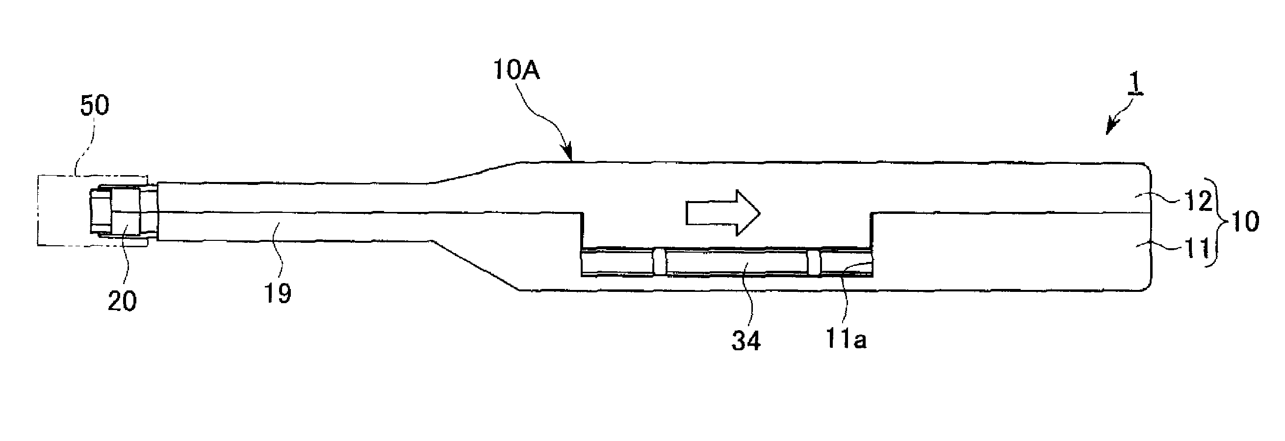
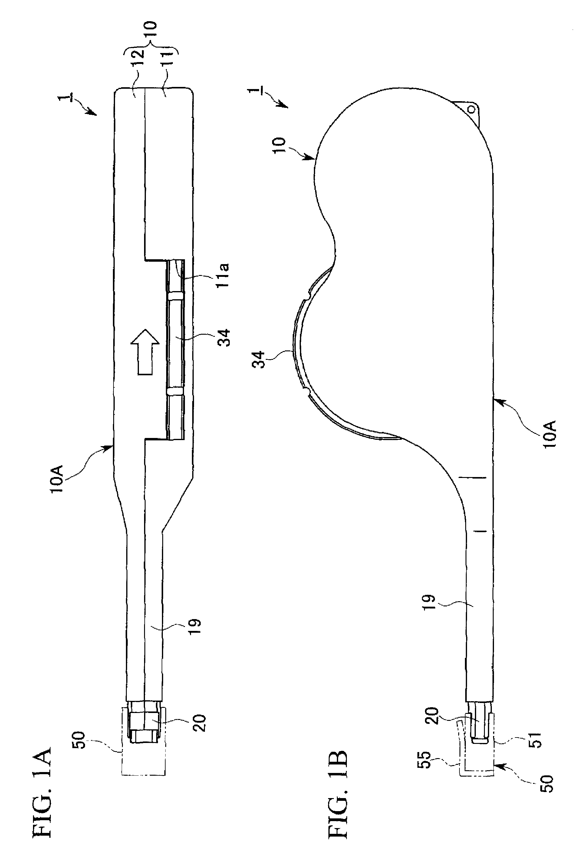
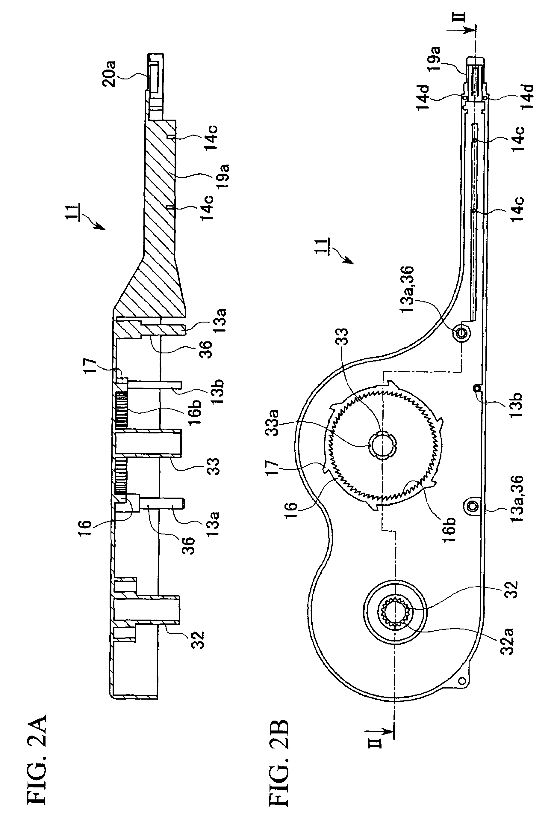
[0139]FIGS. 1 to 22 are views showing a first embodiment of the optical connector cleaning tool (referred to below simply as ‘cleaning tool’) of the present invention.

[0140]As is shown in FIG. 19 and FIG. 21, an optical connector plug 60 (an optical connector—also referred to below simply as an optical plug) and an optical connector adaptor 70 (connector positioning housing—referred to below on occasion simply as an optical adaptor) in which a cleaning tool 1 of the present embodiment is applied here are MPO-type (MPO: multifiber push on) optical connectors which are regulated by JIS C 5982 and the like.

[0141]The optical plug 60 is an optical connector plug having a structure in which an MT-type optical connector ferrule 61 (MT: mechanically transferable—referred to below simply as a ‘ferrule’) w...


PUM


Abstract

A cleaning tool is provided wherein a head unit (4) that is equipped with a supporting portion main body (44), a circular arc-shaped tilt spring (41) that protrudes from this supporting portion main body (44), and a head component (23) that is supported on a protruding distal end (411) of the tilt spring (41) is incorporated into a distal end portion of a protruding portion that protrudes from a tool main body, and wherein the head component (23) is tilted such that the side thereof that protrudes from the protruding distal end (411) of the tilt spring (41) towards the curve apex portion (412) of the tilt spring (41) protrudes towards the rear side, and the head component (23) protrudes towards the front side as it moves towards the opposite side from the protruding distal end (411).

Description

BACKGROUND OF THE INVENTION[0001]1. Field of the Invention[0002]The present invention relates to an optical connector cleaning tool that cleans a joining end surface of an optical connector within a connector positioning housing the feed movement of cleaning medium, and to an optical component cleaning tool that cleans an end surface of an optical component.[0003]Priority is claimed on Japanese Patent Application No. 2006-219696, filed Aug. 11, 2006, and Japanese Patent Application No. 2007-083383, filed Mar. 28, 2007, the contents of which are incorporated herein by reference.[0004]2. Description of the Related Art[0005]As is commonly known, the connecting together of optical connectors within a positioning housing for connectors (may be referred to below simply as a positioning housing) such as an adapter or a receptacle is achieved by aligning together and joining end surfaces of optical fibers that face joining end surfaces of the each optical connector.[0006]When an optical con...

Claims


Application Information

Patent Timeline
IPC IPC(8): A47L25/00
CPCB08B1/008G02B6/3866G02B6/381B08B2240/02B08B1/30
Inventor FUJIWARA, KUNIHIKO
Owner THE FUJIKURA CABLE WORKS LTD
Learn More