Wheel assembly with in-wheel motor

a technology of in-wheel motor and wheel assembly, which is applied in the direction of electric propulsion mounting, electric devices, gearing details, etc., can solve the problem of not easy to supply oil from the oil pump to the motor, and achieve the effect of easy supply of oil and without losing the durability of the oil pump

Active Publication Date: 2008-02-14
TOYOTA JIDOSHA KK
View PDF4 Cites 25 Cited by
  • Summary
  • Abstract
  • Description
  • Claims
  • Application Information

AI Technical Summary

Benefits of technology

[0008]This invention thus provides a wheel assembly with an in-wheel motor (the term “in-wheel motor” in this specification refers to a m

Problems solved by technology

Thus, with this structure it is easy to supply oil from the oil pump to the planetary gear set, but not easy to supply oil from the oil pump to the motor.
In this

Method used


Image

  • Wheel assembly with in-wheel motor
  • Wheel assembly with in-wheel motor
  • Wheel assembly with in-wheel motor

Examples


Embodiment Construction

[0019]In the following description and the accompanying drawings, the present invention will be described in more detail in terms of exemplary embodiments.

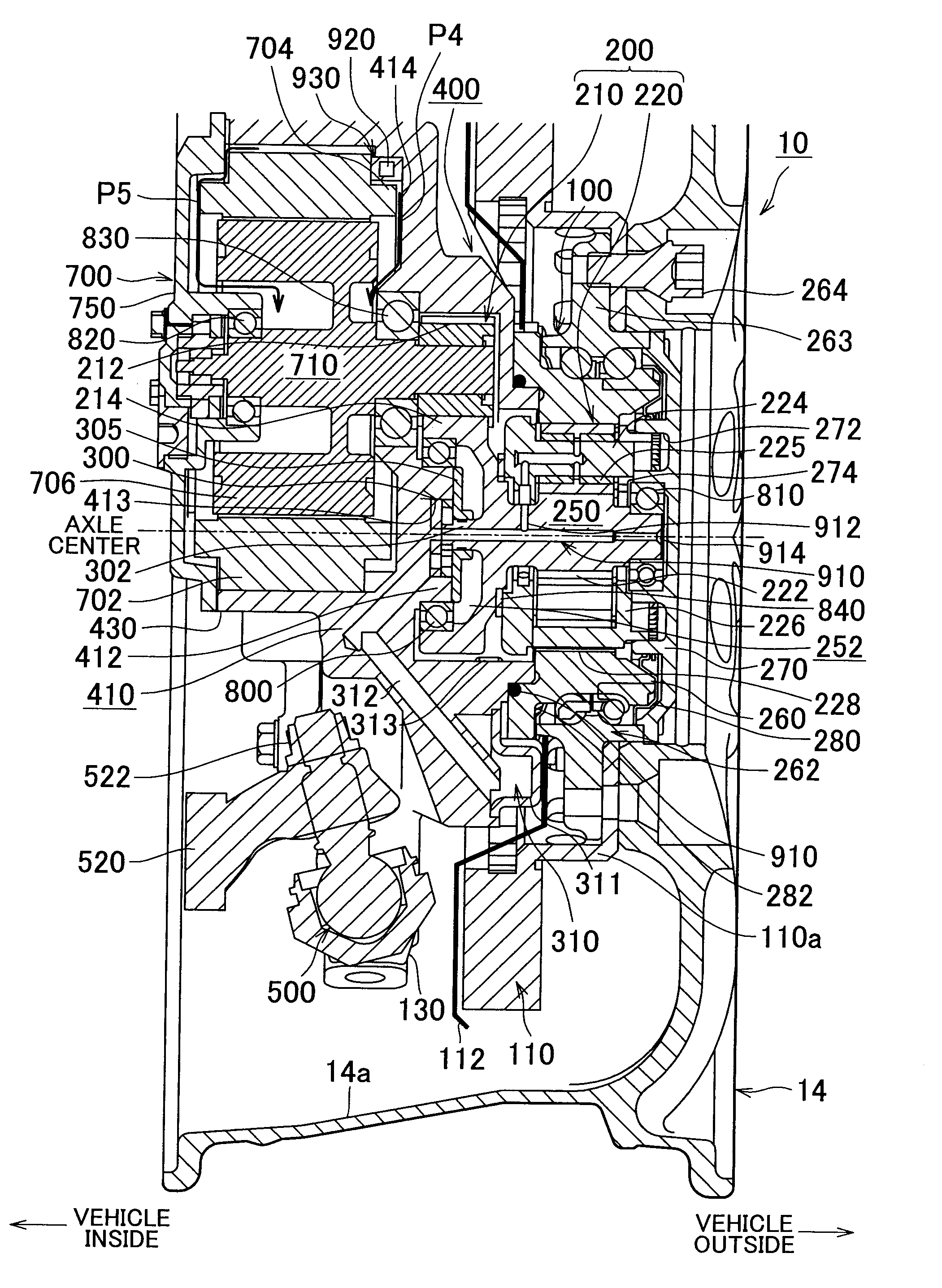
[0020]FIG. 1 is a sectional view of the main structure of a wheel assembly with an in-wheel motor according to one example embodiment of the invention. In the drawing, the tire, as well as the upper ⅓ or so of the wheel, is omitted.

[0021]A tire / wheel assembly 10 includes a wheel 14 to which a tire, not shown, is mounted. As will be described in detail later, the main portions of the constituent elements related to the motor are housed in a space enclosed by a rim inner peripheral surface 14a of the wheel 14. In the following description, the words “inside of the tire / wheel assembly” refer to the generally columnar space that is enclosed by the rim inner peripheral surface 14a of the wheel 14. However, expressions such as “a part is arranged inside the tire / wheel assembly” do not always mean that the entire part is housed completel...


PUM


Abstract

A wheel assembly with an in-wheel motor, which transmits rotational output of an output shaft of a motor to a wheel via a counter gear, is provided with an oil pump that is driven by rotational output of the counter gear and an oil flow path that leads oil from the oil pump to the motor.

Description

INCORPORATION BY REFERENCE[0001]The disclosure of Japanese Patent Application No. 2006-219766 filed on Aug. 11, 2006, including the specification, drawings and abstract is incorporated herein by reference in its entirety.BACKGROUND OF THE INVENTION[0002]1. Field of the Invention[0003]The invention relates to a wheel assembly with an in-wheel motor, which transmits rotational output of the motor to a wheel via a counter gear.[0004]2. Description of the Related Art[0005]Japanese Patent Application Publication No. JP-A-2005-335623, for example, describes a related wheel assembly with an in-wheel motor, which reduces (i.e., slows or decelerates) rotational output of a motor and then transmits it to a wheel. In this wheel assembly with an in-wheel motor, an oil pump is driven by a shaft that rotates at a slowed rate.[0006]However, with the invention described in Japanese Patent Application Publication No. JP-A-2005-335623, a planetary gear set, which serves as the reduction mechanism, is...

Claims


Application Information

Patent Timeline
IPC IPC(8): B60K7/00F16H57/023F16H57/04H02K7/116
CPCF16H57/04B60K2007/0038B60L2220/46B60K7/0015B60K2007/0061B60K17/043B60K17/046
Inventor MURATA, SATOSHITSUCHIDA, MICHITAKAURANO, HIROAKI
Owner TOYOTA JIDOSHA KK
Why Eureka
Try Eureka