
Energy-absorbing padding with staged elements

a technology of energy-absorbing padding and staged elements, which is applied in the direction of vibration dampers, doors, mechanical equipment, etc., can solve the problems of initial stress and peak loading that may exceed design objectives, and achieve the effect of avoiding both the initial stress and initial stress peak, regulating the energy-absorbing capacity of padding, and improving occupant protection

Inactive Publication Date: 2008-02-14
SPINGLER GREGORY +1
View PDF27 Cites 12 Cited by
  • Summary
  • Abstract
  • Description
  • Claims
  • Application Information

AI Technical Summary

Benefits of technology

"The invention is about a type of energy-absorbing padding used in vehicles to protect occupants in the event of an impact. The padding has a unique structure made up of hollow, hemispherical or dome-shaped elements that are integrated with base layers. These elements provide a smooth and progressive impact surface that absorbs energy in a smoother way for the occupant, reducing the initial stiffness and peak stress. The padding can be divided into stages to provide increased energy absorption capability with increasing crush. The size, shape, and number of elements can be customized to enhance occupant safety and provide a predictable post-peak stress response. The invention improves occupant safety and provides a smoother impact for vehicle occupants."

Problems solved by technology

Known designs often employ a plurality of molded frusto-conical or “truncated cone”-shaped energy-absorbing elements or modules projecting from one or both sides of a median plane, resulting in an initial peak of stress and a peak rate of loading that may exceed design objectives.

Method used


Image

  • Energy-absorbing padding with staged elements
  • Energy-absorbing padding with staged elements
  • Energy-absorbing padding with staged elements

Examples


Embodiment Construction

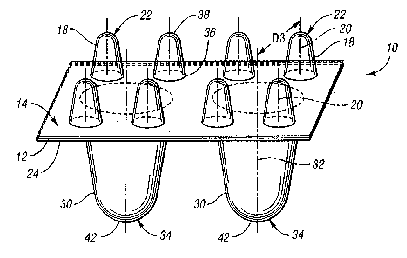
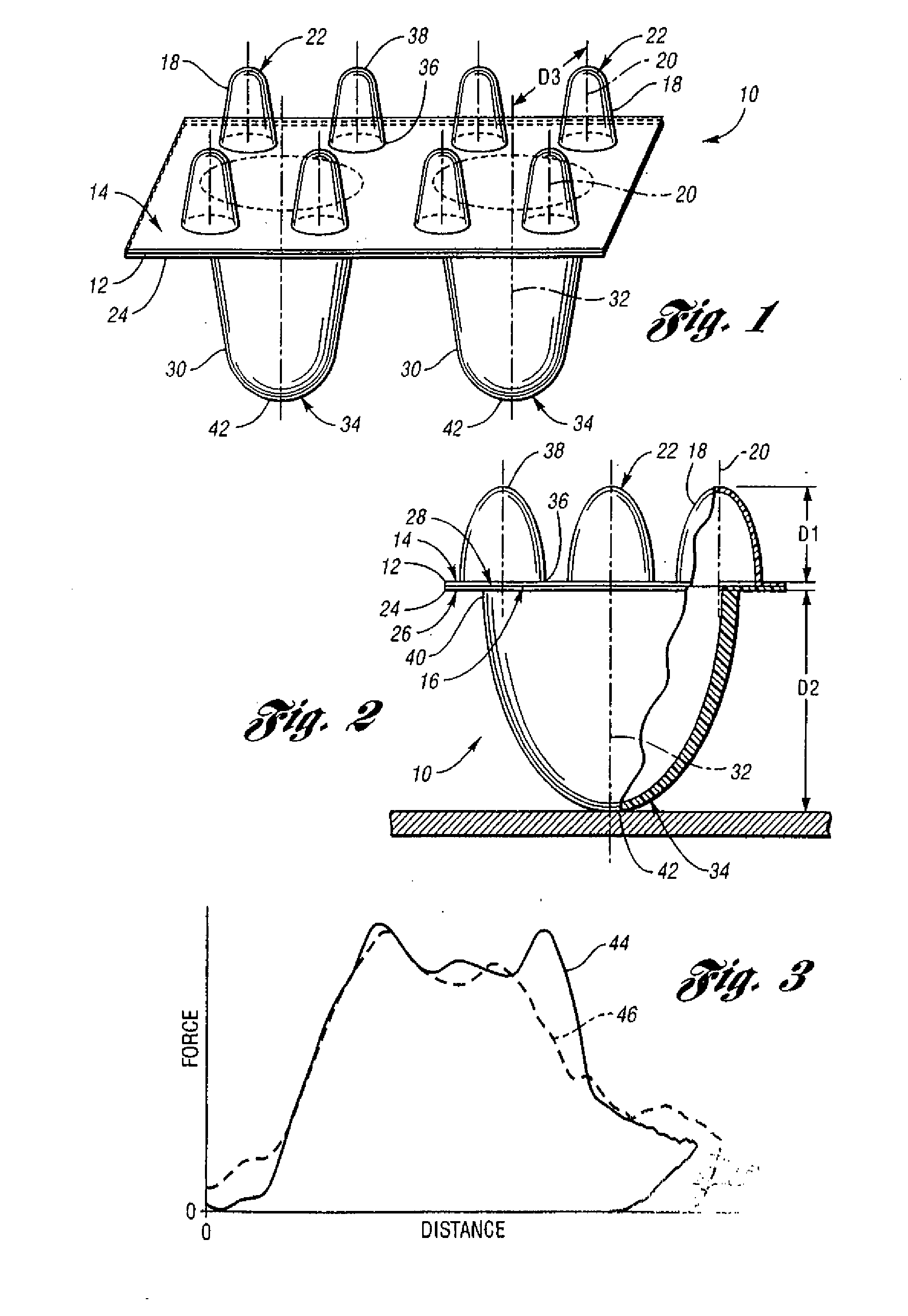
[0021] Referring to FIGS. 1 and 2, a first exemplary energy-absorbing padding 10 for a motor vehicle, for example, adapted to be installed within a vehicle door beneath a “skin” of interior trim (not shown), includes a first or upper base layer 12 having a first face 14, a second face 16, and a plurality of integrally-formed, hollow, first or upper elements 18 projecting from the upper base layer's first face 14 along a first axis 20 to thereby define convex impact surfaces 22 disposed a first distance D1 from the first face 14 of the upper base layer 12. The first padding 10 further includes a second or lower base layer 24 also including a first face 26, a second face 28, and a plurality of integrally-formed, hollow second or upper elements 30 projecting from the lower base layer's first face 26 along a second axis 32 to thereby define convex impact surfaces 34 on the lower layer 24 disposed a second distance D2 from the lower layer's first face 24. The second distance D2 is signif...


PUM


Abstract

An energy-absorbing padding includes multiple stacked base layers, each of which includes a plurality of projecting, hollow, hemispherical or dome-shaped impact-absorbing elements defining respective convex impact surfaces. The elements of a first base layer, which either project in a direction opposite those of at least one other base layer or project in the same direction in a nested relationship, provide a staged response characteristic in which the first elements of a first base layer accommodate initial and off-axis occupant impacts, while the elements of the at least one other layers provide additional stiffness and energy absorption capability subsequent to at least a partial collapse of the first elements. The wall thickness of the elements may advantageously vary, for example, as a function of distance from the base layer, while a plurality of strengthening ribs may advantageously further serve to enhance the energy absorption capacity of the elements.

Description

CROSS-REFERENCE TO RELATED APPLICATION [0001] This application is a continuation of U.S. patent application Ser. No. 10 / 828,804, filed Apr. 20, 2004, the entire contents of which are incorporated by reference.FIELD OF THE INVENTION [0002] The invention relates to energy-absorbing passive safety devices for motor vehicle applications. BACKGROUND OF THE INVENTION [0003] Motor vehicles are often provided with energy-absorbing dashboards and door panels that mitigate injury to vehicle passengers in the event of an accident. The prior art teaches a variety of energy-absorbing structures based on foams, honeycombs or injected parts that are designed to absorb the maximum part of the energy produced during a crash, and to control both the force level and the distance of crush. [0004] Known designs often employ a plurality of molded frusto-conical or “truncated cone”-shaped energy-absorbing elements or modules projecting from one or both sides of a median plane, resulting in an initial peak...

Claims


Application Information

Patent Timeline
Patent Type & Authority Applications(United States)
IPC IPC(8): B60R21/04F16F7/12B60J5/00B60N3/02
CPCB60R21/04F16F7/121B60R21/0428
Inventor SPINGLER, GREGORYDORNIER, LUC
Owner SPINGLER GREGORY
Learn More