Wheel assembly with in-wheel motor

a technology of in-wheel motor and wheel assembly, which is applied in the direction of electric propulsion mounting, electric devices, transportation and packaging, etc., can solve the problems of reducing the space within the wheel, increasing the weight,

Active Publication Date: 2008-02-14
TOYOTA JIDOSHA KK
View PDF11 Cites 19 Cited by
  • Summary
  • Abstract
  • Description
  • Claims
  • Application Information

AI Technical Summary

Benefits of technology

[0007]This invention thus provides a reasonable structure that appropriately arranges bearings provided for an output shaft of a motor and a rotating center shaft of a counter gear, and which can withstand the axial force of the bearings but does not lead to an increase in weight and the like.

Problems solved by technology

However, making the portions that support these bearings extremely strong and rigid by increasing their thickness also increases weight and reduces space within the wheels, which is unreasonable.

Method used


Image

  • Wheel assembly with in-wheel motor
  • Wheel assembly with in-wheel motor
  • Wheel assembly with in-wheel motor

Examples


Embodiment Construction

[0015]In the following description and the accompanying drawings, the present invention will be described in more detail in terms of exemplary embodiments.

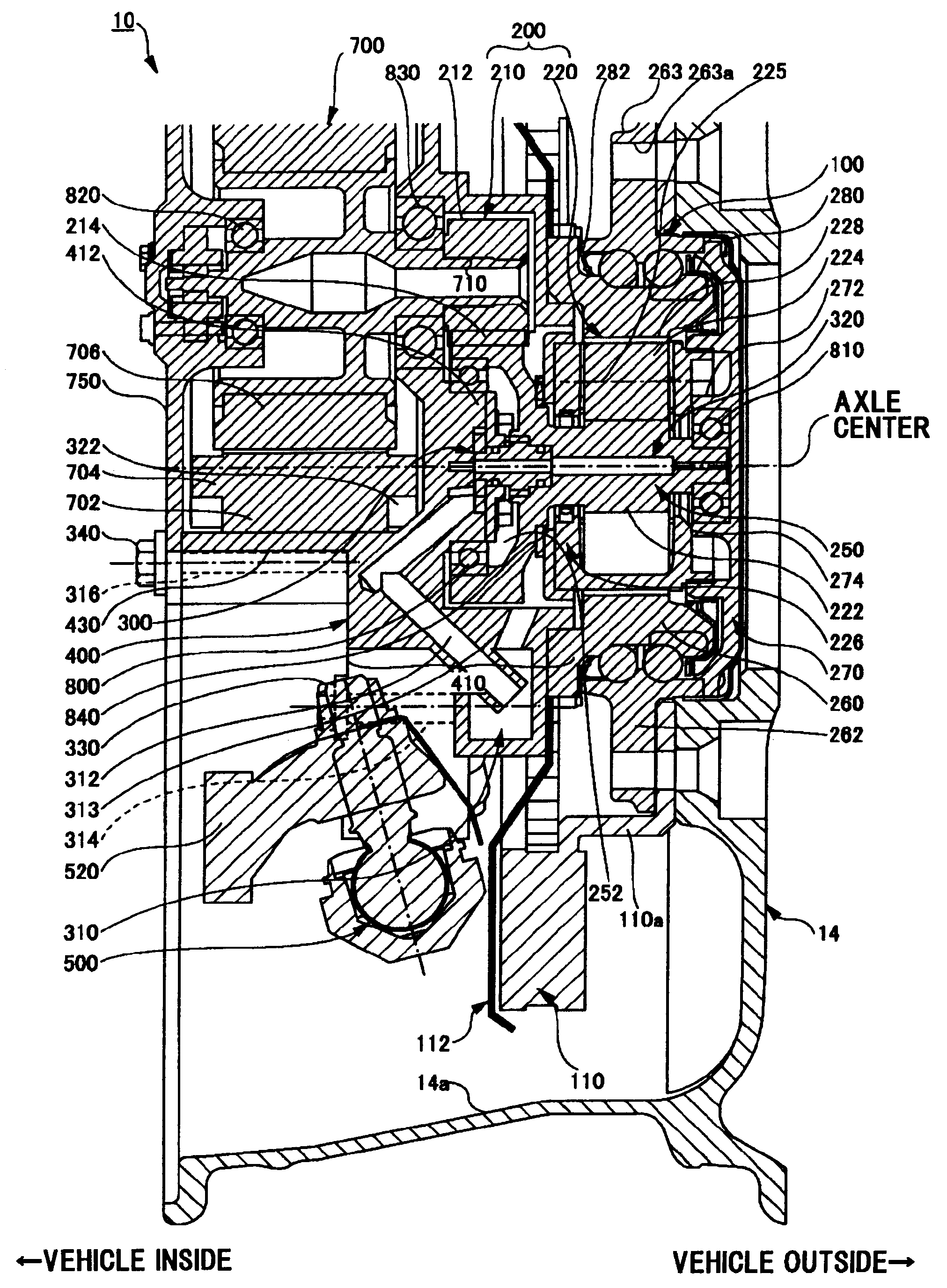
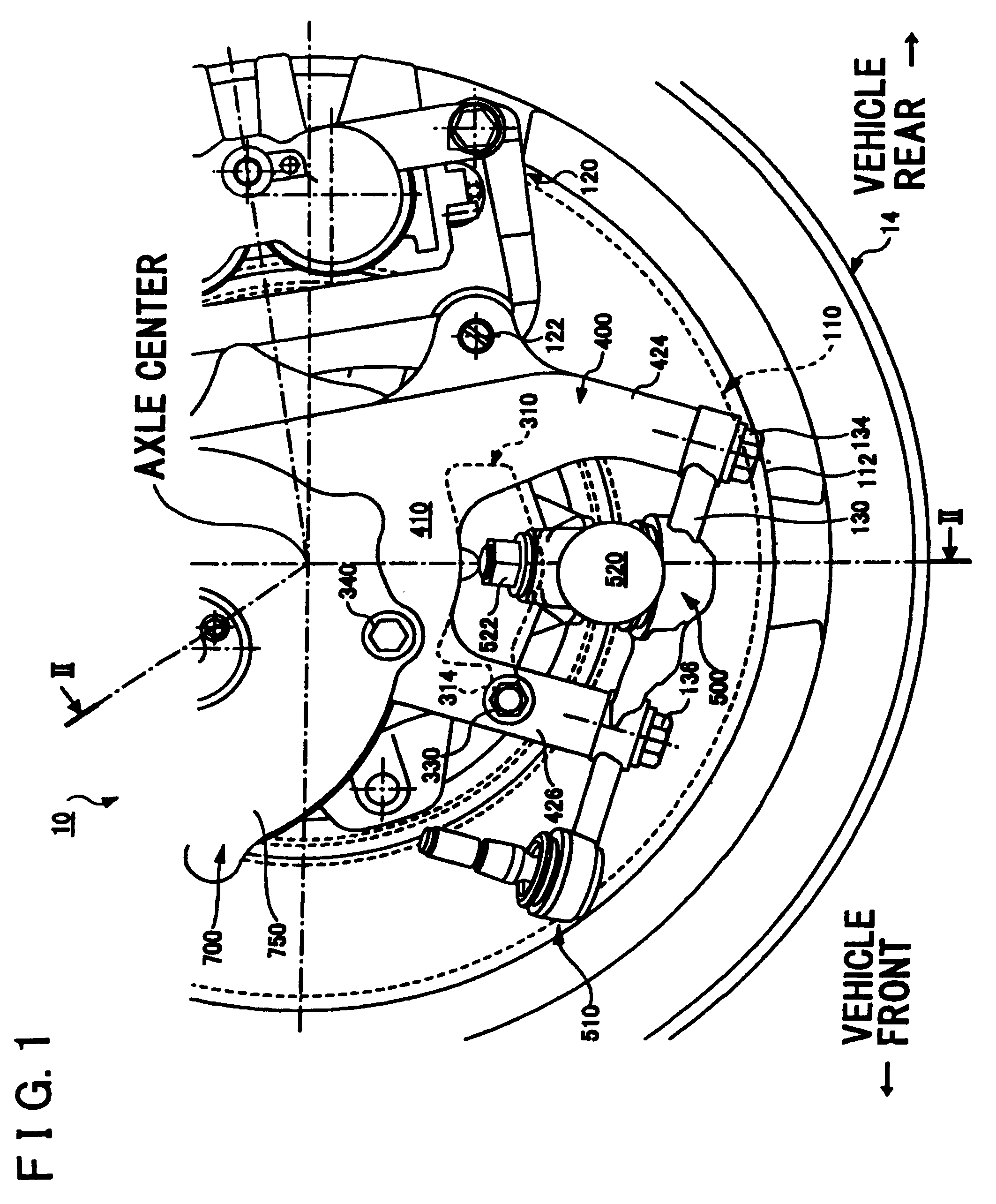
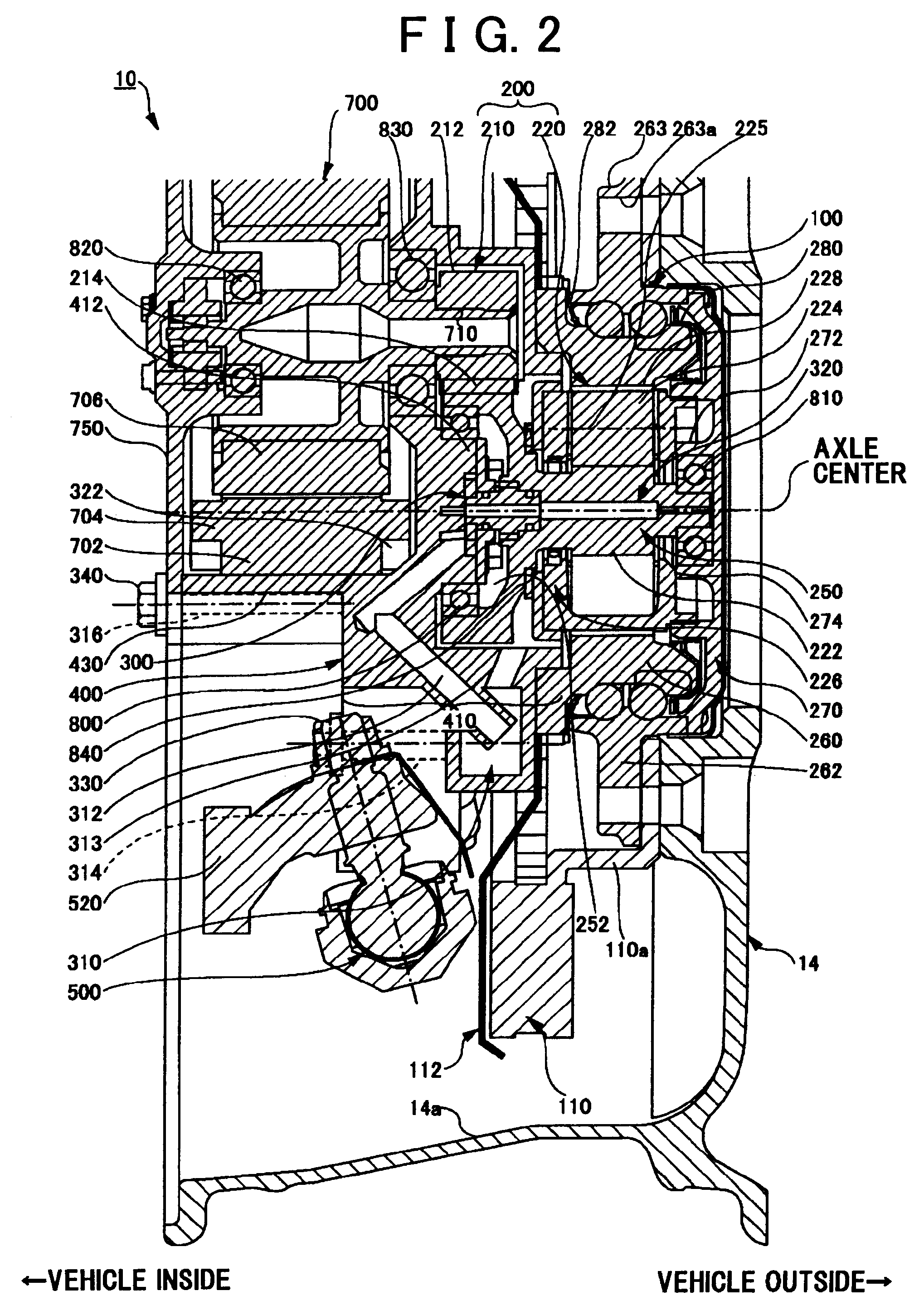
[0016]FIGS. 1 and 2 are views of a wheel assembly with an in-wheel motor (the term “in-wheel motor” in this specification refers to a motor that is housed within a wheel) according to one example embodiment of the invention. FIG. 1 is a view of the wheel assembly from the vehicle inside and FIG. 2 is a sectional view taken along line II-II in FIG. 1. FIG. 3 is a perspective view of an example of a method for connecting an outer race side member 262 to a power transmitting member 270. In FIG. 1, the left side of the drawing corresponds to the front side of the vehicle. In FIGS. 1 and 2, the tire, as well as the upper ⅓ or so of the wheel, is omitted.

[0017]A tire / wheel assembly 10 includes a wheel 14 to which a tire, not shown, is mounted. As will be described in detail later, the main portions of the constituent elements related to...


PUM


Abstract

A wheel assembly with an in-wheel motor, which transmits rotational output of an output shaft of a motor to a wheel via a counter gear, is such that a bearing on a vehicle outside, from among bearings provided on the vehicle inside and the vehicle outside in a vehicle width direction which rotatably support the output shaft of the motor, and a bearing on the vehicle inside, from among bearings provided on the vehicle inside and the vehicle outside in the vehicle width direction which rotatably support a rotating center shaft of the counter gear, are housed inside a main structure portion of a knuckle that defines a load transfer path.

Description

INCORPORATION BY REFERENCE[0001]The disclosure of Japanese Patent Application No. 2006-219762 filed on Aug. 11, 2006, including the specification, drawings and abstract is incorporated herein by reference in its entirety.BACKGROUND OF THE INVENTION[0002]1. Field of the Invention[0003]The invention relates to a wheel assembly with an in-wheel motor, which transmits rotational output of the motor to a wheel via a counter gear.[0004]2. Description of the Related Art[0005]A vehicle having a related wheel assembly with an in-wheel motor that can individually control the braking / driving force of each wheel is known. There are many types of wheel assemblies with in-wheel motors, some of which transmit output from the motor to the wheel via reduction gears, while others transmit output of the motor directly to the wheel using a direct drive method without going through reduction gears. Japanese Patent Application Publication No. JP-A-2004-90822, for example, describes one of the former type...

Claims


Application Information

Patent Timeline
Patent Type & Authority Applications(United States)
IPC IPC(8): B60K7/00
CPCB60G2204/148B60G2204/30B60G2300/50B60K7/0007B62D7/18B60K2007/0038B60K2007/0061B60L2220/46B60K17/046
Inventor MURATA, SATOSHI
Owner TOYOTA JIDOSHA KK
Why Eureka
Try Eureka