Braking pressure control unit for vehicle braking system

a technology of braking system and control unit, which is applied in the direction of braking system, vehicle components, transportation and packaging, etc., can solve the problems of increasing the size and increasing the length of the braking pressure control unit. the effect of reducing the limit of mounting the braking pressure control unit in the engine compartmen

Inactive Publication Date: 2008-02-14
ADVICS CO LTD
View PDF18 Cites 13 Cited by
  • Summary
  • Abstract
  • Description
  • Claims
  • Application Information

AI Technical Summary

Benefits of technology

[0009]The present invention is made in view of the foregoing problems, and has an object to provide a braking pressure control unit for a vehicle, in which an electric motor is arranged at one side of the braking pressure control unit and an electronic control unit is arranged at the other side thereof, so that the electric motor and the electronic control unit oppose to each other, wherein the braking pressure control unit can be made as smaller as possible so that limitations for mounting the braking pressure control unit in an engine compartment may be reduced.

Problems solved by technology

A problem may occur when a size of the braking pressure control unit becomes larger, and when it may become difficult, depending on a vehicle model, to mount the braking pressure control unit in an engine compartment of a vehicle.
However, in the braking pressure control unit, in which the electric motor and the electronic control unit are arranged in the motor shaft direction, as disclosed in the above identified Japanese Patent Publications, a length of the electric motor and the electronic control unit in the motor shaft direction is likely to become longer.
When the electronic control unit, in which such electric parts having large sizes are included, is arranged in the motor shaft direction, the length of the braking pressure control unit becomes inevitably longer.
And it may become more difficult to mount the braking pressure control unit in the engine compartment.

Method used


Image

  • Braking pressure control unit for vehicle braking system
  • Braking pressure control unit for vehicle braking system
  • Braking pressure control unit for vehicle braking system

Examples


Embodiment Construction

[0036]An embodiment of the present invention will be explained with reference to FIGS. 1 to 12 of the attached drawings.

[0037]For the convenience sake of the explanation, sub reference numerals (such as -1, -2, and so on) are added to respective main reference numerals, when there are a plurality of components which are identical or similar to each other, e.g. electromagnetic valves, pumps, and so on. The sub reference numerals are added to the main reference numerals so that the components having the same main reference numerals are distinguished from each other.

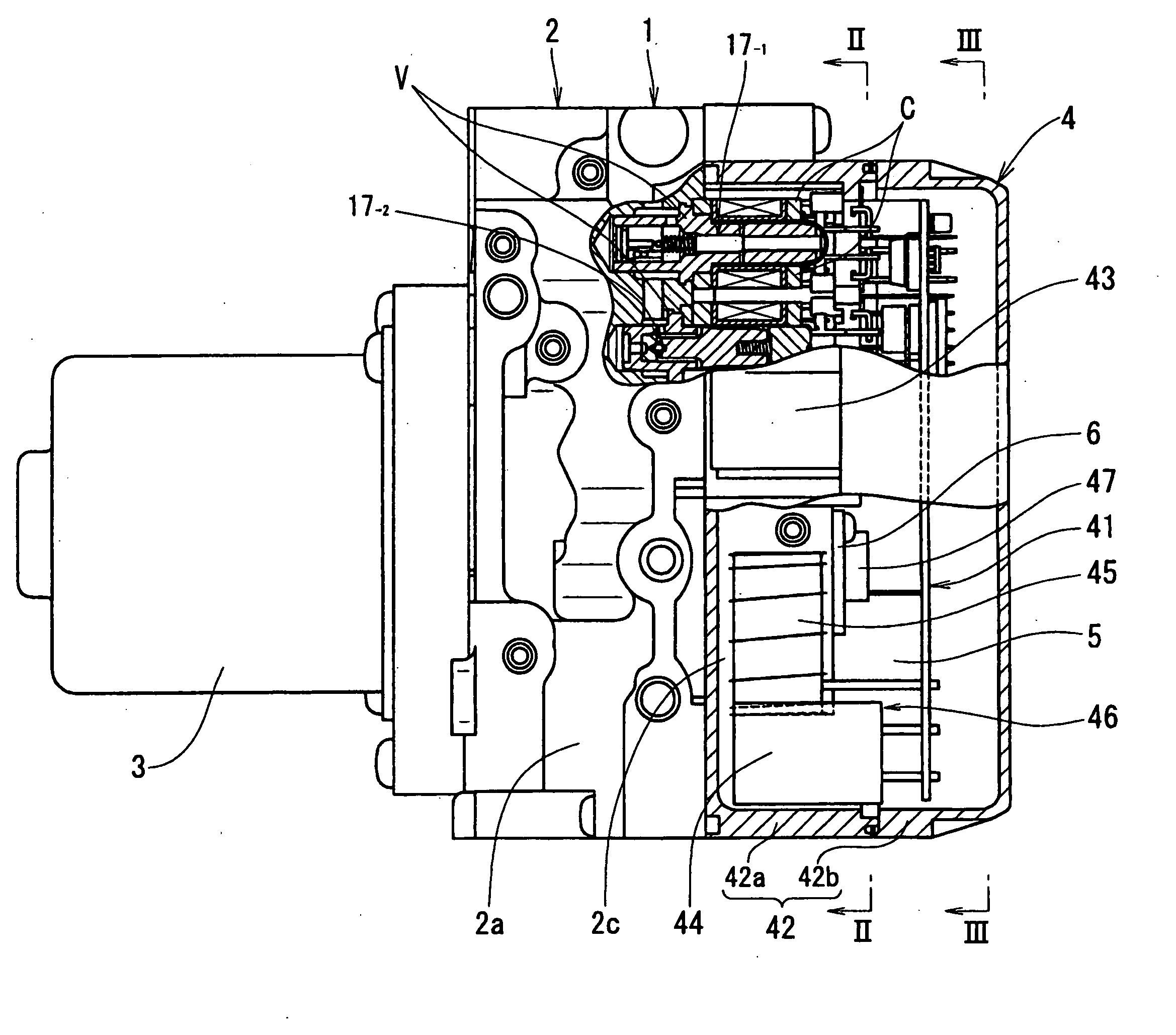
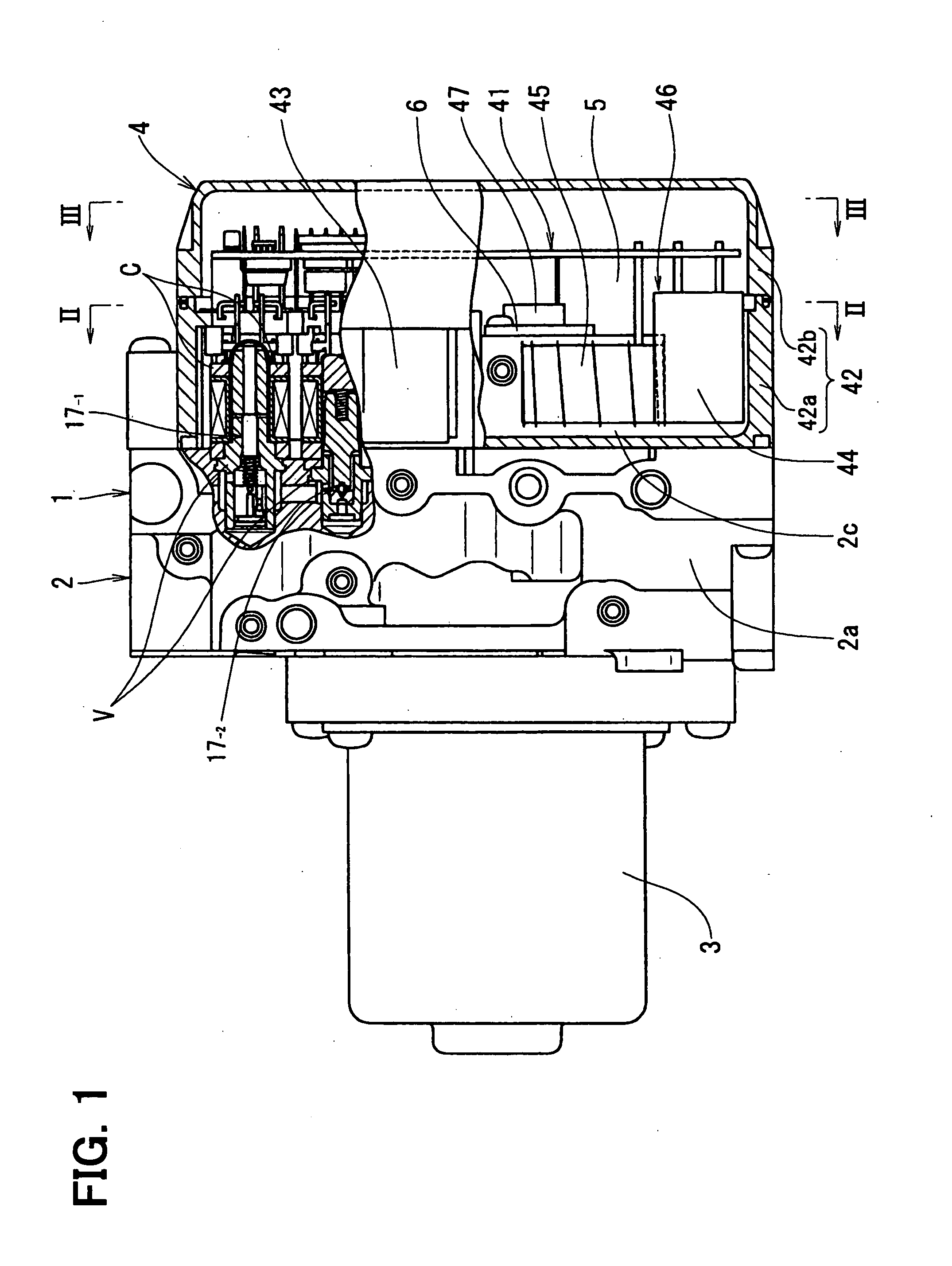
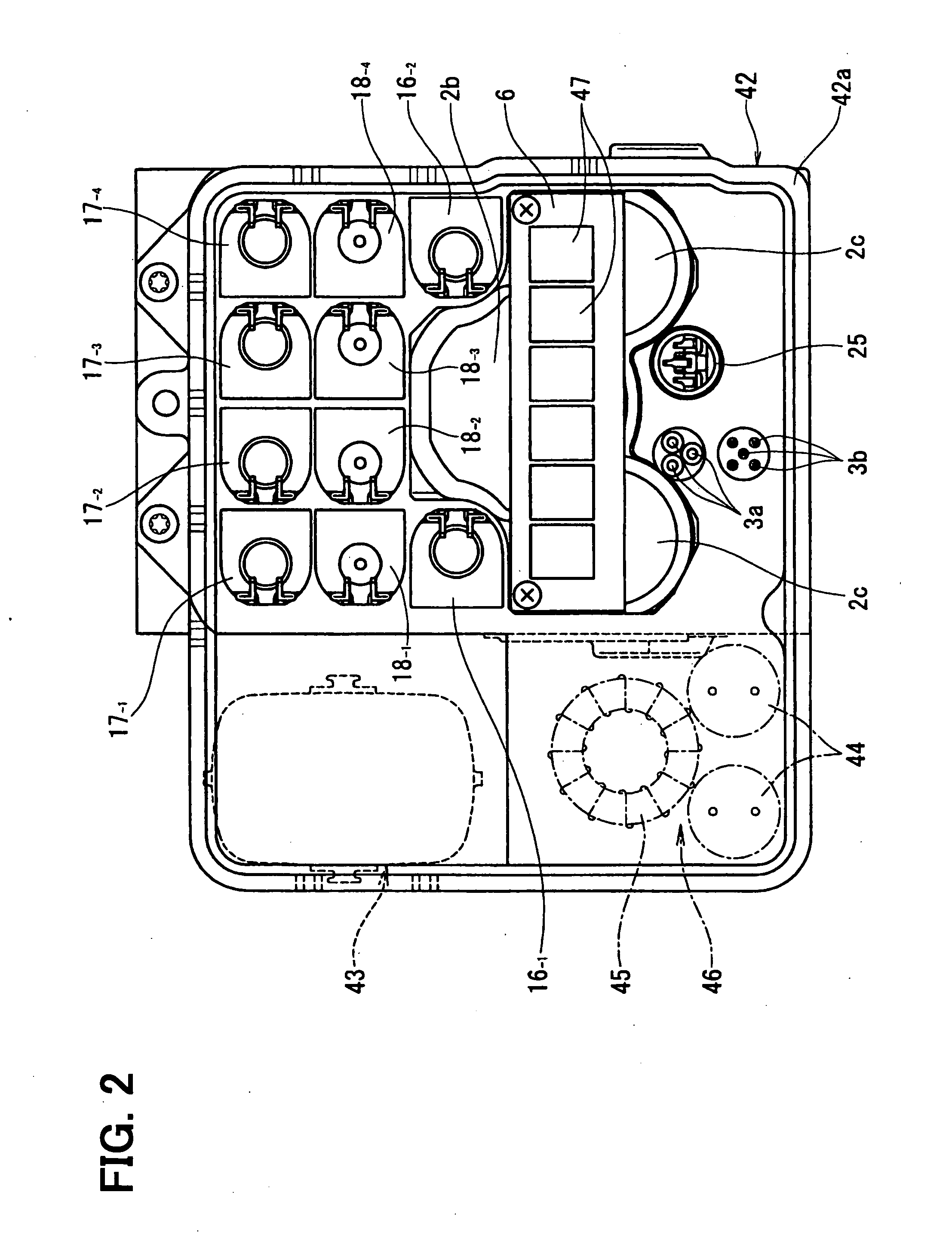
[0038]FIGS. 1 to 3 respectively show a braking pressure control unit 1 for a vehicle braking system according to the embodiment of the present invention. The braking pressure control unit 1 is composed of a hydraulic pressure control block 2, an electric motor 3, and an electronic control unit (ECU) 4.

[0039]FIG. 4 shows an example of a hydraulic circuit for the vehicle braking system. The braking pressure control unit 1 sho...


PUM


Abstract

In a braking pressure control unit for a vehicle braking system, an electric motor is arranged at one side of a hydraulic pressure control block, while electromagnetic valves and an electronic control unit are arranged at the other side of thereof. A connector portion to be connected with an external terminal and an accommodation space are formed in a casing of the braking pressure control unit, such that the connector portion and the accommodation space protrude outwardly from an outer periphery of the hydraulic pressure control block in a direction perpendicular to a direction of a motor shaft of the electric motor, and that the accommodation space is neighboring to the connector portion. And a large-sized electrical part included in a motor driving circuit is accommodated in the accommodation space.

Description

CROSS REFERENCE TO RELATED APPLICATION[0001]This application is based on Japanese Patent Application Nos. 2006-220169 filed on Aug. 11, 2006, and 2007-131485 filed on May 17, 2007, the disclosures of which are incorporated herein by reference.FIELD OF THE INVENTION[0002]The present invention relates to a braking pressure control unit for a vehicle braking system, which controls brake fluid pressure for wheel cylinders in accordance with control signals from an electronic control unit.BACKGROUND OF THE INVENTION[0003]A braking pressure control unit is applied to a vehicle braking system, which generally has a function for an anti-lock braking control (ABS), a function for a vehicle stability control (ESC), and so on. The braking pressure control unit is composed of a combination of a hydraulic pressure control block in which a pump and electromagnetic valves are assembled in a housing thereof, an electric motor for driving the pump, and an electronic control unit having a motor drivi...

Claims


Application Information

Patent Timeline
Patent Type & Authority Applications(United States)
IPC IPC(8): B60T13/16
CPCB60T8/368
Inventor SAKAI, MORIHARUYOSHIJIMA, TETSUYA
Owner ADVICS CO LTD
Why Eureka
Try Eureka