Volume sensor: data fusion-based, multi-sensor system for advanced damage control

a multi-sensor system and volume sensor technology, applied in the field of volume sensor, can solve the problems of poor response time, high false alarm rate, and overall sensitivity problems

Inactive Publication Date: 2008-02-14
UNITED STATES OF AMERICA
View PDF11 Cites 124 Cited by
  • Summary
  • Abstract
  • Description
  • Claims
  • Application Information

AI Technical Summary

Benefits of technology

[0015] Disclosed is a method for detecting an event while discriminating against false alarms in a monitored space using at least one sensor suite to acquire signals, transmitting the signals to a sensor system device where the signal is processed into data packets, transmitting the data packets to a data fusion device, where...

Problems solved by technology

Conventional systems typically have disadvantages that include high false alarm rates, poor response times, and overall sensitivity problems.
Some recently proposed systems incorporate different types of point detectors into a neural network, which may achieve better accuracy and response times than individual single sensors alone but lack the faster response time possible with remote sensing. e.g., optical detection.
A drawback is that it is most effective with a direct line of sight (LOS) to the source, therefore a single detector may not provide effective coverage for a monitored space.
OFDs are effective at monitoring a wide area, but these are primarily flame detectors and not very sensitive to smoldering fires.
These are also not effective for detecting hot objects or reflected light.
Other approaches such as thermal imaging using a mid infrared camera are generally too expensive for most applications.
These are most effective at identifying smoke and less successful at detecting flame, particularly for small, emergent source (either directly or indirectly viewed, or hot objects).
The main exception is that the video-based systems do not respond to small flaming fires as well as ionization smoke detectors.
Its disadvantages include that it does not sense in the visible or near-IR region, and it does not dis...

Method used


Image

  • Volume sensor: data fusion-based, multi-sensor system for advanced damage control
  • Volume sensor: data fusion-based, multi-sensor system for advanced damage control
  • Volume sensor: data fusion-based, multi-sensor system for advanced damage control

Examples


Embodiment Construction

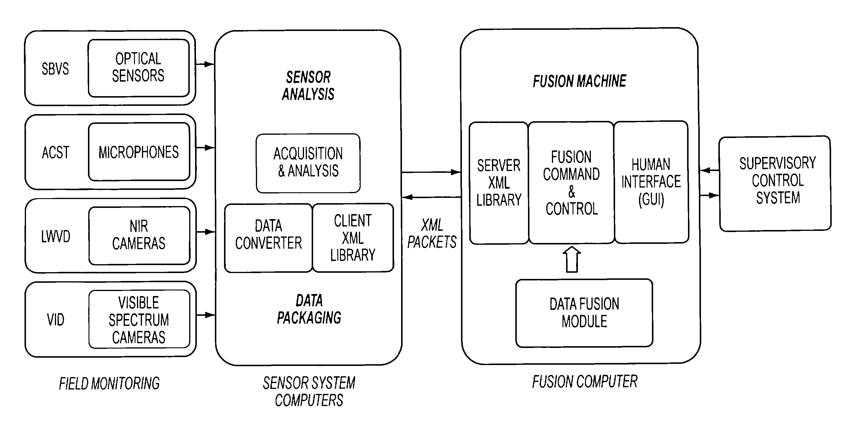
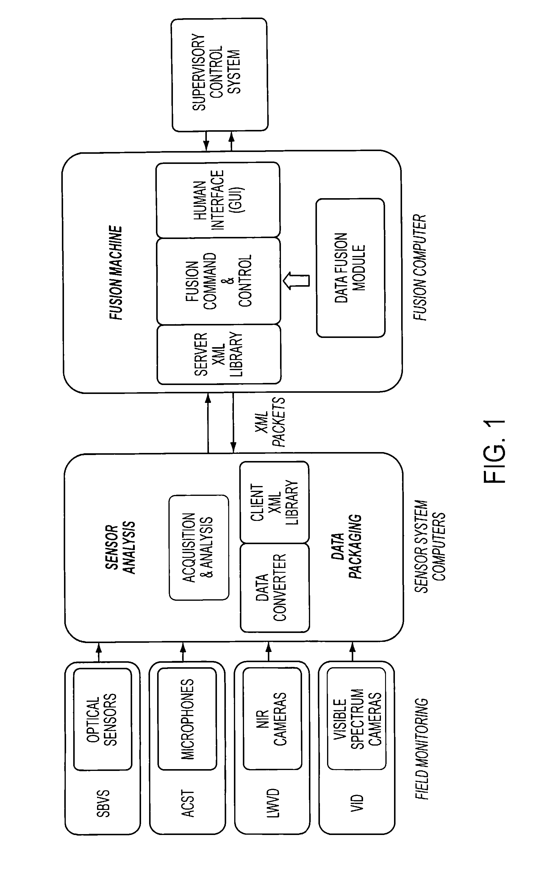
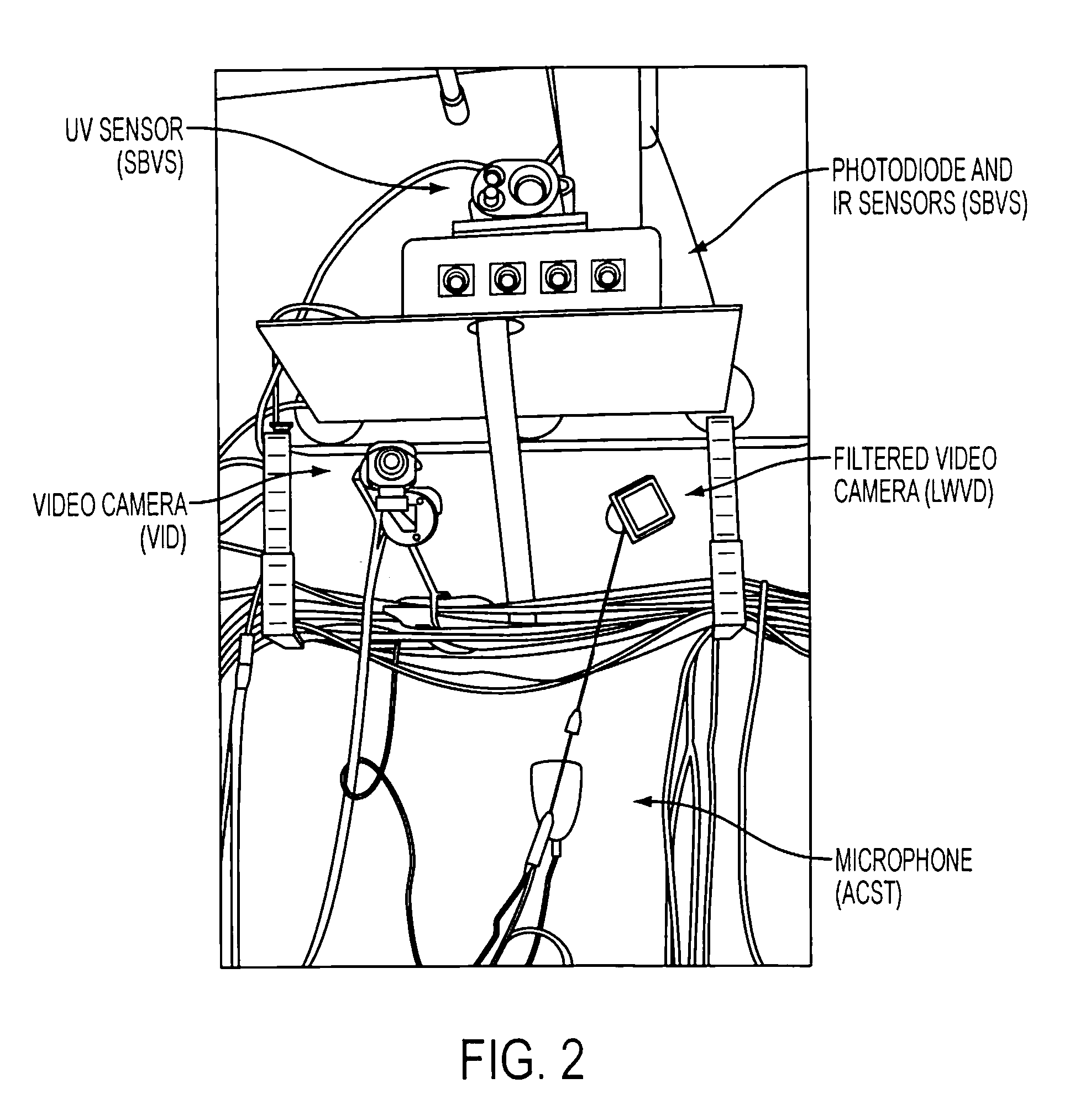
[0023] An affordable, automated, real-time detection system has been developed to address the need for detection capabilities for standoff identification of events within a space, such as fire, explosions, pipe ruptures, and flooding level. The system employs smart data fusion to integrate a diverse group of sensing modalities and network components for autonomic damage control monitoring and real-time situational awareness, particularly on U.S. Navy ships. This Volume Sensor system comprises spectral and acoustic sensors, new video imaging techniques, and image recognition methods. A multi-sensory data fusion approach is used to combine these sensor and algorithm outputs to improve event detection rates while reducing false positives, providing a system with detection capabilities for standoff identification of events within a space, such as fire, explosions, pipe ruptures, and flooding level. The Volume Sensor system required the development of an efficient, scalable, and adaptabl...


PUM


Abstract

Provided a system and method for detecting an event while discriminating against false alarms in a monitored space using at least one sensor suite to acquire signals, transmitting the signals to a sensor system device where the signal is processed into data packets, transmitting the data packets to a data fusion device, where the data packets are aggregated and algorithmic data fusion analysis is performed to generate threat level information. The threat level information is distributed to a supervisory control system where an alarm level can be generated when predetermined criteria are met to indicate the occurrence of an event in the monitored space.

Description

CROSS-REFERENCE TO RELATED APPLICATIONS [0001] This application is a Non-Prov of Prov (35 USC 119(e)) application 60 / 821,476 filed on Aug. 4, 2006.BACKGROUND OF THE INVENTION [0002] Fire detection systems and methods are employed in most commercial and industrial environments, as well as in shipboard environments that include commercial and naval maritime vessels. Conventional systems typically have disadvantages that include high false alarm rates, poor response times, and overall sensitivity problems. Although it is desirable to have a system that promptly and accurately responds to a fire occurrence, it as also necessary to provide one that is not activated by spurious events, especially if the space contains high-valued, sensitive materials or the release of a fire suppressant is involved. [0003] Humans have traditionally been the fire detectors used on most Navy ships. They are multi-sensory detection systems combining the sense of smell, sight, hearing, and touch with a very s...

Claims


Application Information

Patent Timeline
IPC IPC(8): G08B21/00
CPCG08B17/00G08B29/188G08B25/00G08B25/002
Inventor ROSE-PEHRSSON, SUSAN L.WILLIAMS, FREDERICKOWRUTSKY, JEFFREY C.GOTTUK, DANIEL T.STEINHURST, DANIEL A.MINOR, CHRISTIAN P.WALES, STEPHEN C.
Owner UNITED STATES OF AMERICA
Why Eureka
Try Eureka