Imaging apparatus and endoscope apparatus using the same

a technology of endoscope and endoscope, which is applied in the field of imaging equipment, can solve the problems of increasing the size of the endoscope, difficult to satisfy the demand for decreasing the size, and difficulty in obtaining the still image with a high definition, so as to reduce light incidence and improve the resolution of the still image

Inactive Publication Date: 2008-02-14
PANASONIC CORP
View PDF4 Cites 12 Cited by
  • Summary
  • Abstract
  • Description
  • Claims
  • Application Information

AI Technical Summary

Benefits of technology

[0044]As described above, in the present invention, after the completion of the light exposure for obtaining the still image, the illumination light source is turned OFF, thereby suppressing light incidence into the solid-state imaging device. Thus, according to the imaging apparatus of the present invention and the endoscope apparatus having the same, frame read-out can be achieved without having a light shielding member such as a mechanical shutter, and as a result, a resolution of the still image can be improved.

Problems solved by technology

Thus, in the above-described imaging apparatus, the still image with a vertical resolution that is only a half of the pixels in number is obtained, and it is difficult to obtain the still image with a high definition.
However, in order to mount the mechanical shutter, a space for mounting the mechanical shutter itself and the driving apparatus for driving the mechanical shutter is necessary.
Thus, in the case of applying the imaging apparatus of Conventional Example 2 to an endoscope, a problem of increasing a size of the endoscope occurs, and it becomes difficult to satisfy the demand for decreasing the size.
It is easy to mount the mechanical shutter in an apparatus having a size that is larger than the endoscope, such as a digital still camera and a camcorder, but it is difficult to mount it in an endoscope apparatus.
Moreover, the mechanical shutter has a mechanical structure, in which a structural failure is likely to occur.

Method used


Image

  • Imaging apparatus and endoscope apparatus using the same
  • Imaging apparatus and endoscope apparatus using the same
  • Imaging apparatus and endoscope apparatus using the same

Examples


embodiment 1

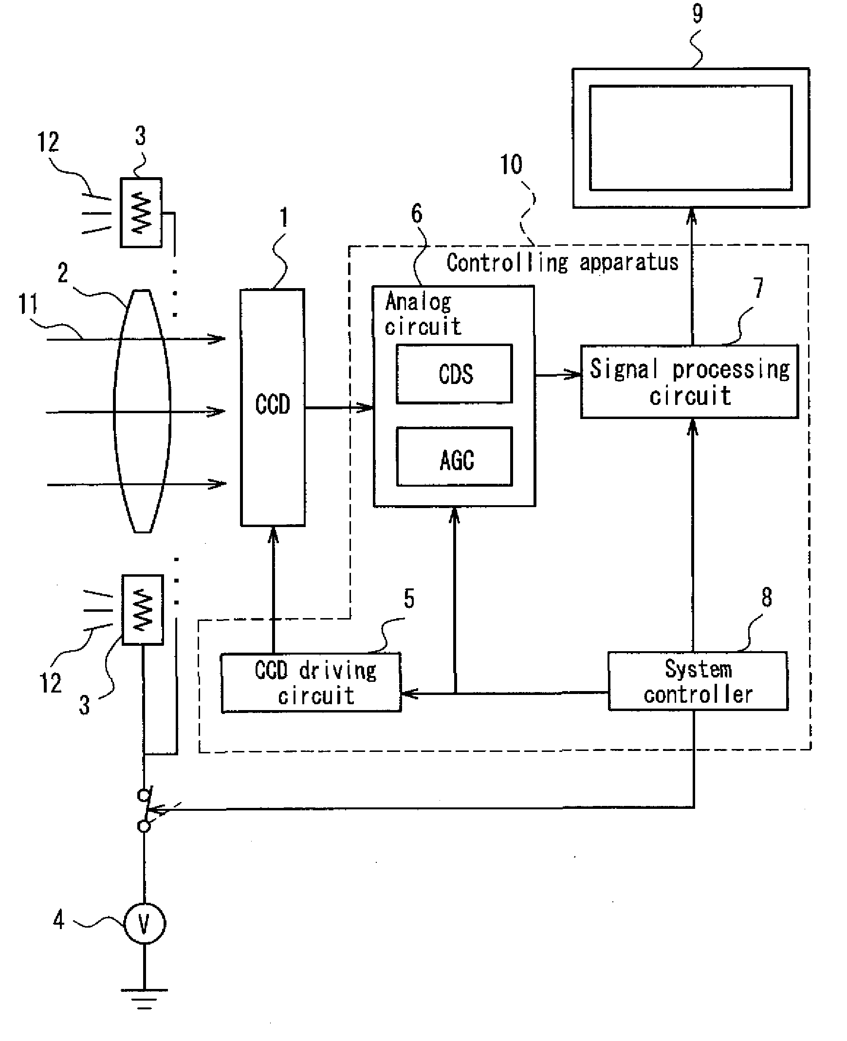
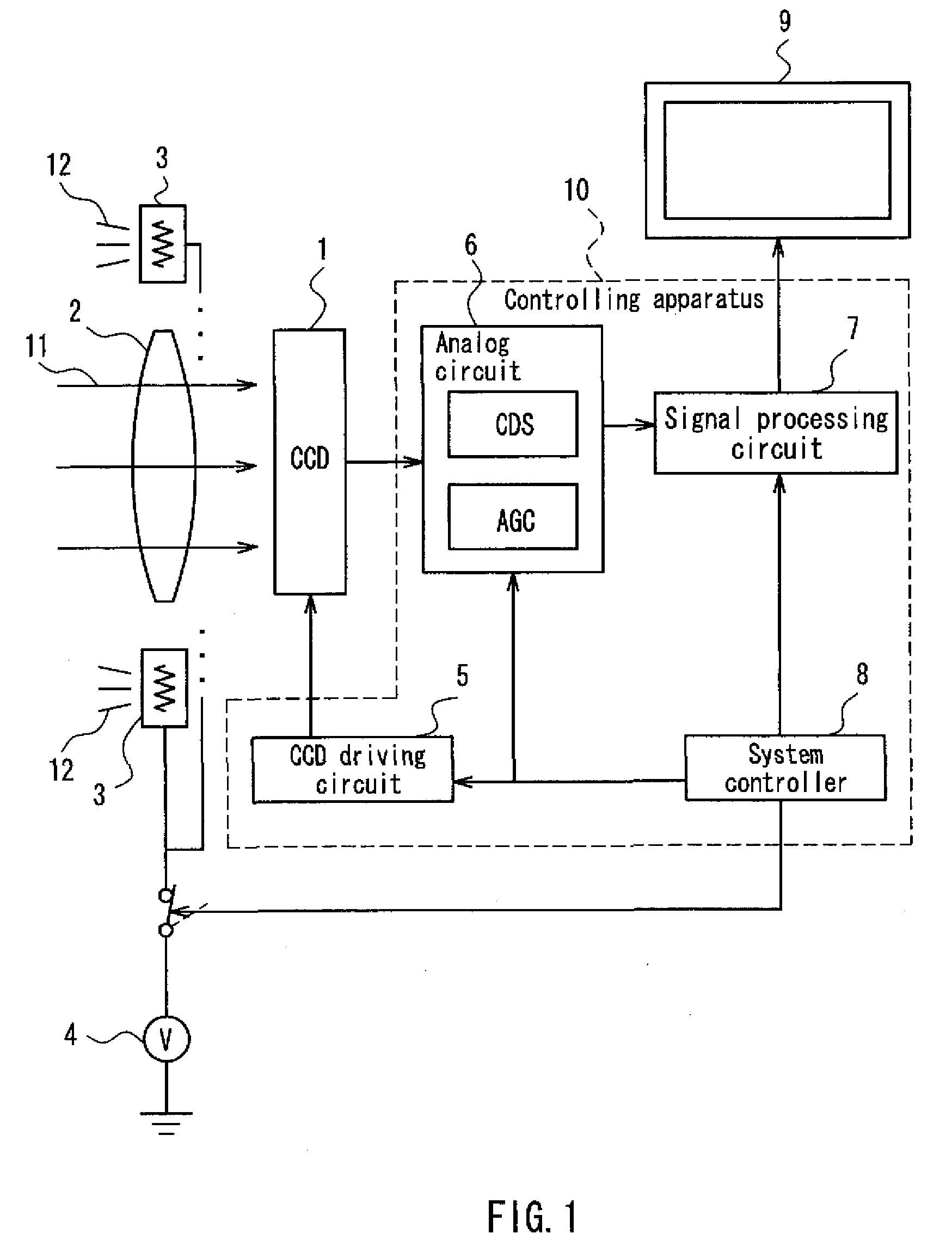
[0082]An imaging apparatus and an endoscope apparatus according to Embodiment 1 of the present invention will be described below with reference to FIGS. 1 to 4. Firstly, a structure of the imaging apparatus according to Embodiment 1 will be described with reference to FIG. 1. FIG. 1 is a structural view schematically showing the structure of the imaging apparatus according to Embodiment 1 of the present invention.

[0083]The imaging apparatus according to Embodiment 1 constitutes a part of the endoscope apparatus (see FIG. 4), and shoots a moving image and a still image in a dark space where external light hardly reaches, similarly to the imaging apparatus of Conventional Example 1 shown in FIG. 19 in Background Art. Also in Embodiment 1, similarly to Conventional Example 1, a CCD type imaging device (CCD) 1 of an interline transfer type is used as the solid-state imaging device.

[0084]Specifically, as shown in FIG. 1, the imaging apparatus of Embodiment 1 is provided with the CCD 1, a...

embodiment 2

[0109]Next, an imaging apparatus and an endoscope apparatus according to Embodiment 2 of the present invention will be described with reference to FIGS. 5 and 6. FIG. 5 is an explanatory view conceptually showing an operation of a solid-state imaging device that constitutes the imaging apparatus according to Embodiment 2 of the present invention. FIG. 5A shows the operation thereof at a time of shooting a moving image, and FIG. 5B shows the operation thereof at a time of shooting a still image.

[0110]The imaging apparatus of Embodiment 2 is distinctive from the imaging apparatus of Embodiment 1 shown in FIG. 1 in the processing that is performed inside the apparatus at a time of shooting a moving image. Except for this point, the imaging apparatus of Embodiment 2 is similar to the imaging apparatus of Embodiment 1 shown in FIG. 1. Moreover, the endoscope apparatus of Embodiment 2 has a structure that is similar to the endoscope apparatus of Embodiment 1 shown in FIG. 4. The distincti...

embodiment 3

[0118]Next, an imaging apparatus and an endoscope apparatus according to Embodiment 3 of the present invention will be described with reference to FIGS. 7 and 8. FIG. 7 is an explanatory view conceptually showing an operation of a solid-state imaging device that constitutes the imaging apparatus according to Embodiment 3 of the present invention. FIG. 7A shows the operation thereof at a time of shooting a moving image, and FIG. 7B shows the operation thereof at a time of shooting a still image.

[0119]The imaging apparatus of Embodiment 3 also is distinctive from the imaging apparatus of Embodiment 1 shown in FIG. 1 in the processing that is performed inside the apparatus at the time of shooting a moving image. Except for this point, the imaging apparatus of Embodiment 3 is similar to the imaging apparatus of Embodiment 1 shown in FIG. 1. Moreover, the endoscope apparatus of Embodiment 3 also has a structure that is similar to the endoscope apparatus of Embodiment 1 shown in FIG. 4. T...


PUM


Abstract

An imaging apparatus that can shoot a moving image and a still image includes: a CCD 1; an illumination light source 3 for illuminating a subject; and a controlling apparatus 10 for controlling the CCD 1 and the illumination light source 3. The CCD 1 includes: a plurality of photoelectric conversion parts that are arranged in matrix; and a vertical charge transfer part for reading out a charge that is accumulated in each of the photoelectric conversion parts, the controlling apparatus 10 allows the vertical charge transfer part to read out the charge in a state where the illumination light source 3 is ON at a time of shooting the moving image, and when an instruction for shooting the still image is provided, the controlling apparatus turns OFF the illumination light source 3 after completion of light exposure for obtaining the still image, allows the vertical charge transfer part to read out all of the charges by dividing the charges into a plurality of fields while the illumination light source 3 is OFF, and synthesizes the charges that are read out separately by the respective fields so as to generate one still image.

Description

BACKGROUND OF THE INVENTION[0001]1. Field of the Invention[0002]The present invention relates to an imaging apparatus that is provided with a solid-state imaging device such as a CCD (a charge coupled device) type imaging device and a MOS type imaging device, and particularly relates to an imaging apparatus that is provided with an auxiliary light source for enabling to shoot an image under an environment with an insufficient luminosity.[0003]2. Description of Related Art[0004]A solid-state imaging device such as a CCD type imaging device and a MOS type imaging device is utilized not only for a digital still camera and a camcorder, but also as an imaging device of an endoscope apparatus. Generally, an endoscope apparatus is used for shooting an image in a space where ambient light hardly reaches, such as an inside of a human body and an inside of a pipeline, and thus is provided with an illumination light source for irradiating the subject.[0005]Moreover, since a space where an endo...

Claims


Application Information

Patent Timeline
Patent Type & Authority Applications(United States)
IPC IPC(8): A61B1/04H04N5/235H04N5/335H04N5/341H04N5/347H04N5/3728H04N5/376
CPCH04N5/23245H04N2005/2255H04N5/2354H04N23/555H04N23/667H04N23/74A61B1/00H04N23/00
Inventor YAMADA, TOHRUTERANISHI, NOBUKAZU
Owner PANASONIC CORP
Why Eureka
Try Eureka