
Image processing system, display device, program, and information recording medium

a technology of image processing and display device, applied in the field of image processing system, a display device, a program, and an information recording medium, can solve the problems of inability to simply combine control methods and use, inability to acquire sufficient contrast, and inability to simply acquire control methods, so as to prevent the generation of image flickering and prevent image flickering

Inactive Publication Date: 2008-02-14
SEIKO EPSON CORP
View PDF3 Cites 27 Cited by
  • Summary
  • Abstract
  • Description
  • Claims
  • Application Information

AI Technical Summary

Benefits of technology

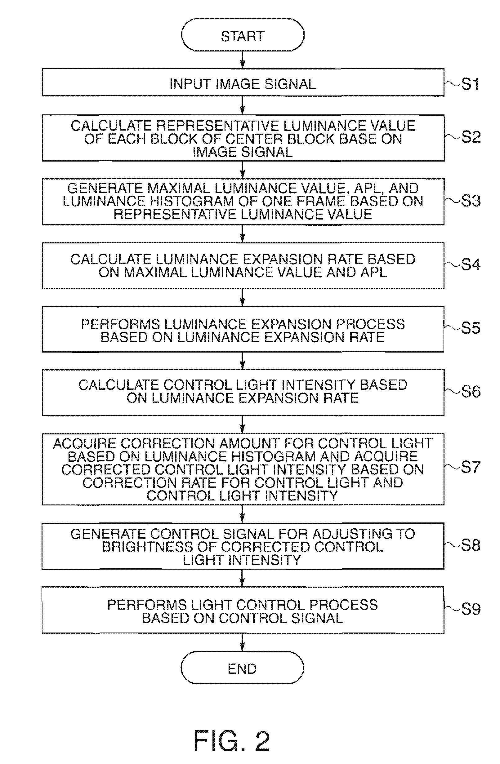
The invention provides an image processing system, display device, program, and information storing medium that can increase the contrast of an image by dimmer control and display an image with proper brightness even in a case where a bright image is displayed. The system uses an image characteristic information generating unit to calculate the maximal luminance value, APL, and luminance histogram of an image based on the image signal. A luminance expansion rate calculating unit is then used to calculate the luminance expansion rate based on the maximal luminance value and APL. A control light intensity generating unit generates the control light intensity based on the maximal luminance value and APL or the luminance expansion rate. A control light intensity regulating unit corrects the control light intensity based on the luminance histogram. The system can increase the contrast of an image by controlling the control light intensity and reducing the luminance of pixels with high luminance levels. The system can also adjust the luminance expansion rate based on the change in the luminance expansion rate of previous frames.

Problems solved by technology

There is a problem in that sufficient contrast cannot be acquired due to the leakage of light which is generated from various optical elements constructing an optical system or stray light in the image display devices.
Since the luminance of the white color is always constant in the image display devices, when white color areas increase, the screen becomes too bright to watch.
Since the controlling methods are conflicting with each other, the controlling methods cannot be simply combined together for being used.

Method used


Image

  • Image processing system, display device, program, and information recording medium
  • Image processing system, display device, program, and information recording medium
  • Image processing system, display device, program, and information recording medium

Examples


first embodiment

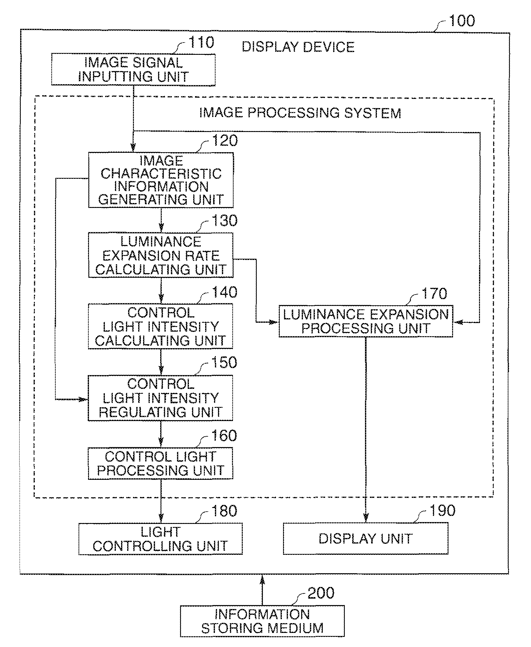
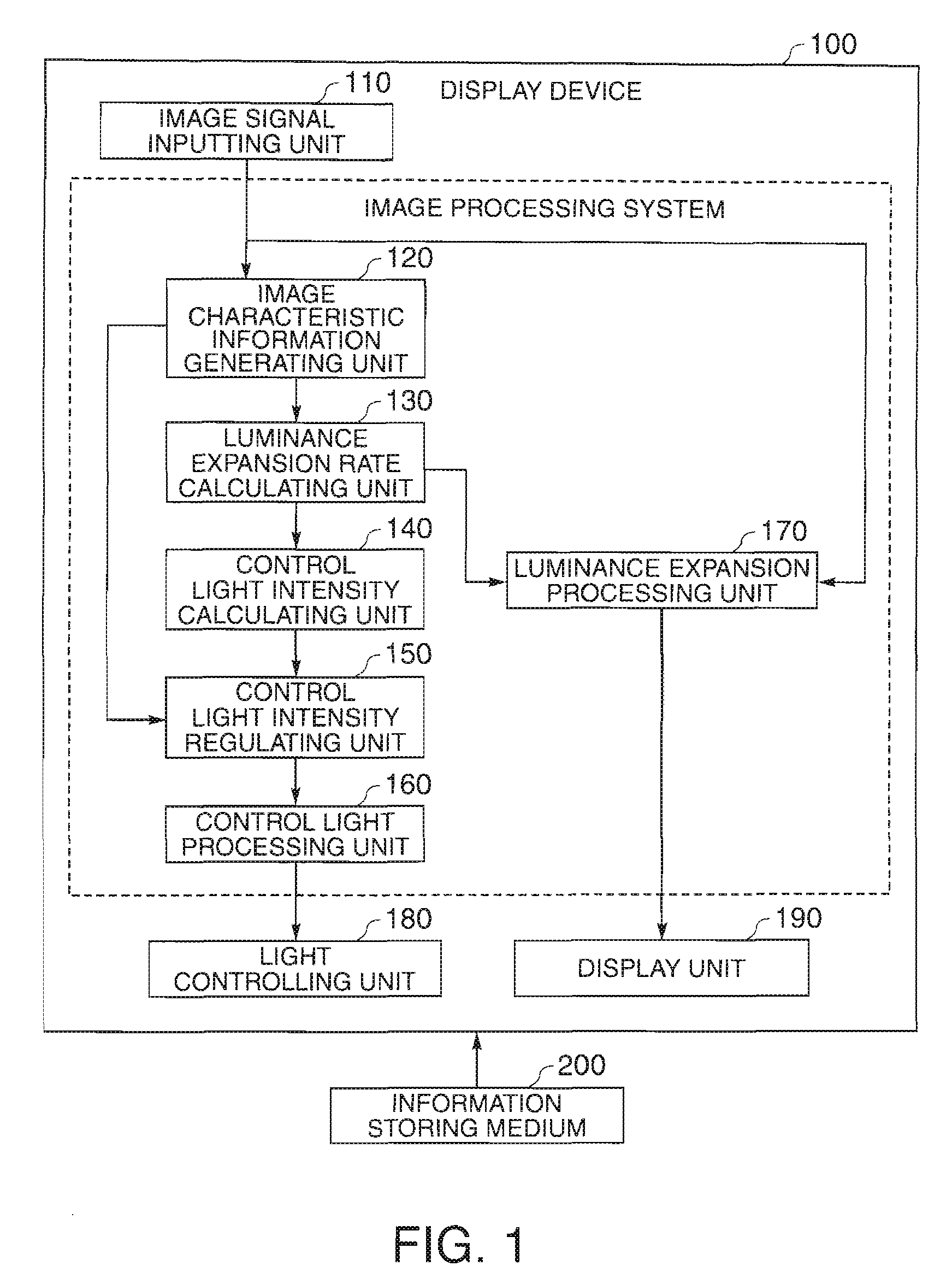
[0041]FIG. 1 is a diagram showing functional blocks of a display device 100 according to this embodiment of the invention.

[0042]The display device 100 includes an image signal input unit 110 which inputs an image signal (for example, an RGB signal), an image characteristic information generating unit 120 which acquires a maximal luminance value (white peak level, WP), an APL (Average Picture Level), and a luminance histogram in one frame based on the image signal, and a luminance expansion rate calculating unit 130 which calculates the luminance expansion rate based on the maximal luminance value and the APL.

[0043]In addition, the display device 100 includes a control light intensity calculating unit 140 which calculates the control light intensity based on the luminance expansion rate, a control light intensity regulating unit 150 which corrects the control light intensity based on a luminance histogram to generate a corrected control light intensity, a control light processing uni...

second embodiment

[0085]In the second embodiment, the control light intensity calculating unit 140 is configured to acquire the control light intensity from the control light intensity LUT based on the maximal luminance value WP and the APL.

[0086]FIG. 9 is a table showing an example of control light intensity LUT500 according to this embodiment of the invention.

[0087]According to control light intensity LUT500, when WP is small, a small value, compared with a case where WP is large, is set, and when the APL is small, a small value, compares with a case where the APL is large, is set. As described above, the control light intensity LUT500 is configured to increase the control light intensity when the image 300 is bright.

[0088]The operation of the second embodiment is the same as that of the first embodiment except that the control light intensity 140 acquires control light intensity from the control light intensity LUT based on the maximal luminance value WP and the APL and that the luminance expansio...

third embodiment

[0090]While the control light intensity regulating unit 150 acquires the corrected control light intensity using the equation “corrected control light intensity KL′=F×KL” in the first and second embodiments, the control light intensity regulating unit 150 in the third embodiment acquires the corrected control light intensity using the equation “corrected control light intensity KL′=KL+CL”.

[0091]As described above, the control light intensity regulating unit 150 can use not only a correction rate F of the corrected control light intensity KL′ but also an absolute amount CL of the corrected control light intensity. In this case, the control light intensity regulating unit 150 may perform an adjustment process, so that the calculated result is in the range of 0 to 1.


PUM


Abstract

An image processing system is disclosed. The image processing system includes an image characteristic information generating unit for calculating a maximal luminance value, an APL, and a luminance histogram of one frame based on an image signal to be displayed, a luminance expansion rate calculating unit for calculating a luminance expansion rate based on the maximal luminance level and the APL, a luminance expansion processing unit for performing a luminance expansion process on the image signal based on the luminance expansion ratio, a control light intensity calculating unit for calculating control light intensity based on the maximal luminance value and the APL or the luminance expansion rate, a control light intensity regulating unit for correcting the control light intensity based on the luminance histogram and generating corrected control light intensity, and a control light processing unit for generating a control signal for controlling a light controlling unit based on the corrected control light intensity, wherein the control light intensity regulating unit acquires the number of pixels having a luminance value equal to or greater than a first predetermined value based on the luminance histogram and generates the corrected control light intensity such that the luminance is decreased when a ratio of the number of the pixels to the total number of the pixels is equal to or greater than a second predetermined value.

Description

BACKGROUND[0001]1. Technical Field[0002]The present invention relates to an image processing system, a display device, a program, and an information storing medium for controlling the brightness of an image.[0003]2. Related Art[0004]Recently, direct-vision or projection type image display devices using liquid crystals nave penetrated into the market. As for the projection type, the projection type image display devices using DMDs (Digital Micromirror Device) along with the projection type image display devices using liquid crystals are available as products in the market. DMD is a trademark of U.S. Texas Instruments Incorporated.[0005]There is a problem in that sufficient contrast cannot be acquired due to the leakage of light which is generated from various optical elements constructing an optical system or stray light in the image display devices. Since the luminance of the white color is always constant in the image display devices, when white color areas increase, the screen bec...

Claims


Application Information

Patent Timeline
Patent Type & Authority Applications(United States)
IPC IPC(8): H04N5/243H04N23/76
CPCG06T5/40G09G3/20G09G2320/0271G09G2320/0626G06T5/009G09G2360/16H04N9/3155H04N9/3197G09G2320/066G06T5/92
Inventor NOBORI, TATSUHIKO
Owner SEIKO EPSON CORP
Learn More