
Method for Particle Size and Concentration Measurement

Active Publication Date: 2008-02-14
PARTICLE MEASURING SYST
View PDF5 Cites 32 Cited by
  • Summary
  • Abstract
  • Description
  • Claims
  • Application Information

AI Technical Summary

Benefits of technology

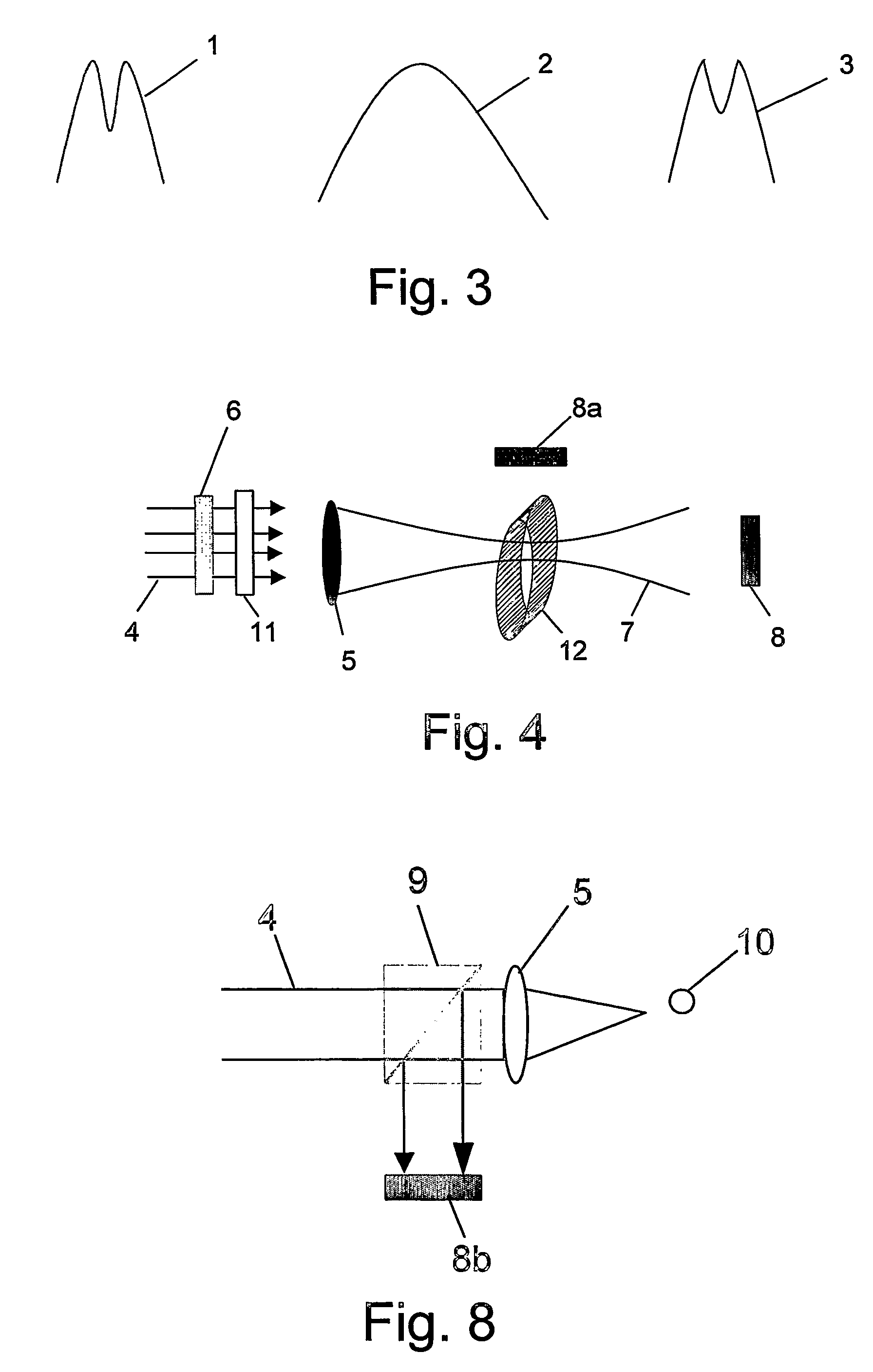
[0033]In another embodiment of the invention the particle size is determined in a transmission mode where the forward scattered light from said particle interferes with the synthesized, non-Gaussian laser beam thus achieving increased sensitivity in transmission mode.

Problems solved by technology

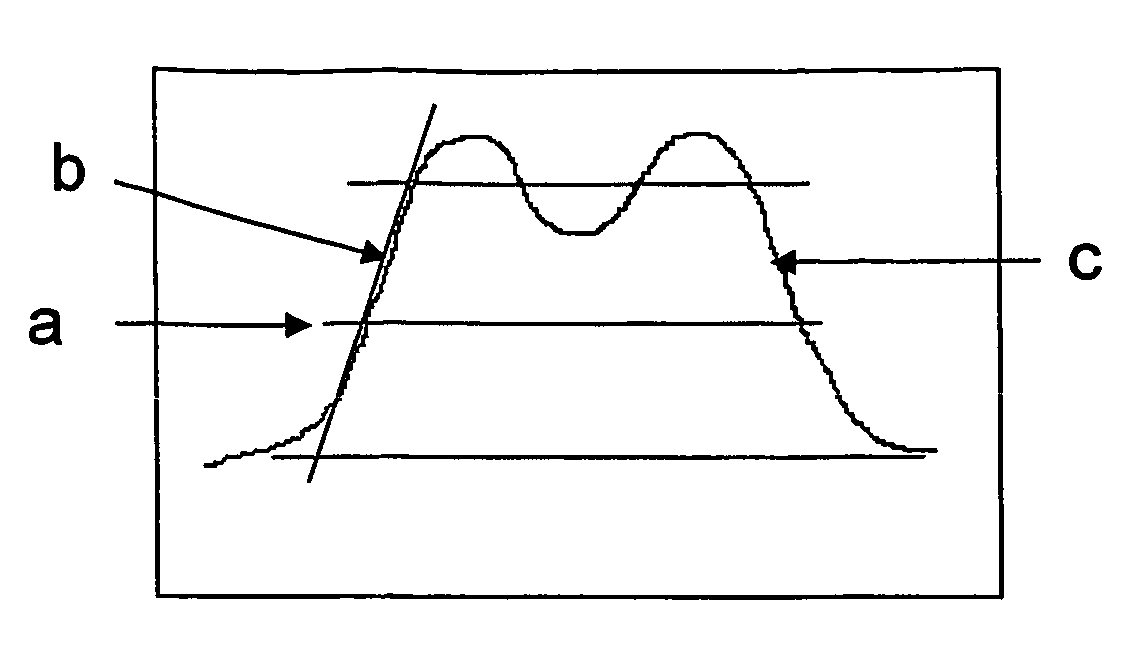
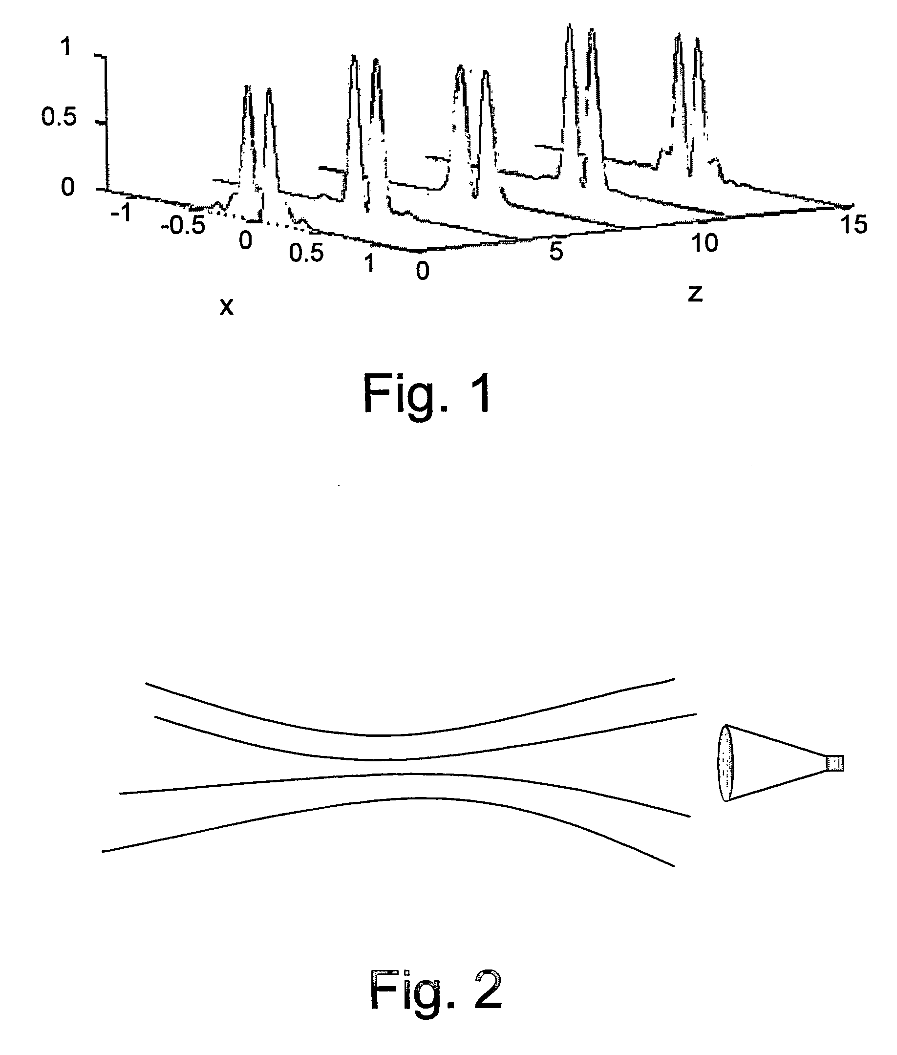
The limitation as described hereinabove in the background results from the inherent Gaussian beam profile of the laser beam.

Method used


Image

  • Method for Particle Size and Concentration Measurement
  • Method for Particle Size and Concentration Measurement
  • Method for Particle Size and Concentration Measurement

Examples


examples

A. Beam Synthesis

[0109]Both circular (doughnut) and linear (slit) dark beams have been synthesized and their measured energy distributions compared with the theoretical analysis.

[0110]FIG. 9A shows one possible pattern used to realize the circular dark beam. FIG. 9B shows the pattern of FIG. 9A illuminated with a Gaussian beam (a HeNe laser). FIG. 10 is a photograph of the far field image showing the zero and first order of the energy pattern. FIG. 11 shows the corresponding energy distribution.

[0111]FIG. 12 shows a comparison of the experimental results to the simulation for the circular beam shown in FIG. 10. The image on the left side of FIG. 12 is the simulation and the image on the right side of FIG. 12 shows the experimental results. In the two graphs, the vertical axis represents the relative intensity and distance in pixels is measured along the horizontal axis.

[0112]A linear dark beam is generated by using a spatial light filter that has a phase shift of Π on half of its pl...


PUM


Abstract

The present invention provides method of particle size and concentration measurement that comprises the steps of: providing a focused, synthesized, non-Gaussian laser beam, causing the beam to interact with the particles, measuring the interaction signal and the number of interactions per unit time of the beam with the particles, and using algorithms to map the interaction signals to the particle size and the number of interactions per unit time to the concentration. The particles are fluid borne, airborne, or on a surface and have a size ranging from sub-micron to thousands of microns. In a preferred embodiment of the invention, the focused, synthesized, non-Gaussian laser beam is a dark beam. The non-Gaussian beam can be generated by employing a mask over a Gaussian laser beam or by directly modifying the laser cavity or by combining the beams from several lasers. The measurements can be made using the duration of interaction with a scanning beam, including dark field. The invention further provides a system for particle size and concentration measurement.

Description

FIELD OF THE INVENTION[0001]The present invention is related to the field of measuring particle size and concentration. More specifically it relates to the use of optical methods for measuring particle size and concentration. The particles could be liquid borne, airborne or on a surface.BACKGROUND OF THE INVENTION[0002]Publications and other reference materials referred to herein are incorporated herein by reference in their entirety and are numerically referenced in the following text and respectively grouped in the appended Bibliography, which immediately precedes the claims.[0003]Many techniques exist for particle size and concentration analysis (PSA), they can be reviewed for reference in the book by Terry Alan (1) “Introduction to Particle Size Analysis”. The most commonly used techniques are optical, based on the interaction of the measured particles with laser radiation. Especially when approaching the particle size range around 1 micron and below, most of these techniques su...

Claims


Application Information

Patent Timeline
IPC IPC(8): G01N21/00G01N15/02G02B26/08G01N15/14
CPCG01N15/1459G01N2015/1493G01N2015/145
Inventor SHAMIR, JOSEPHKARASIKOV, NIR
Owner PARTICLE MEASURING SYST
Learn More