
Variable Capacitance with Dielectric Fluid

a dielectric fluid and capacitance technology, applied in the field of electronic devices of capacitor type having a variable capacitance, can solve the problems of not solving the problem of non-stability of the capacitance, limiting the range of capacitance variation, and not ensuring the stability of the capacitance valu

Inactive Publication Date: 2008-02-14
COMMISSARIAT A LENERGIE ATOMIQUE ET AUX ENERGIES ALTERNATIVES
View PDF8 Cites 17 Cited by
  • Summary
  • Abstract
  • Description
  • Claims
  • Application Information

AI Technical Summary

Benefits of technology

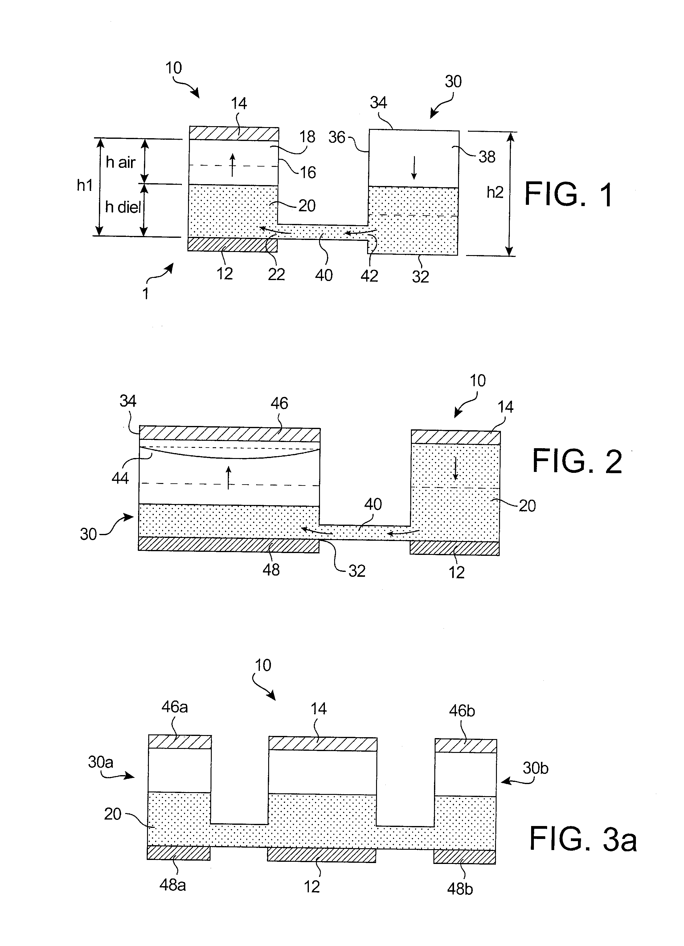
[0016] The displacement of the fluid is achieved through the intermediary of a membrane present in the second cavity, the deflection of which pushes the dielectric fluid towards the first cavity, and thereby increases the capacitance defined by the two capacitor electrodes.

Problems solved by technology

However, the value of the capacitance is defined by the air gap between the two electrodes: since an electrode is suspended, the stability of the capacitance value is not assured.
Moreover, variable capacitances with air gap variation by electrostatic actuation have a major problem: at one third of the initial air gap, the electrostatic forces become preponderant compared to the return forces, and there is an abrupt bonding of the electrodes (“pull-in” phenomenon), which considerably limits the range of capacitance variation.
Different solutions have been envisaged to mitigate this problem, but the results are complex from a technological point of view, and do not resolve the problem of non stability of the capacitance.
However, thermal actuation has the major drawback of heavy consumption.
This type of structure has different problems, and particularly high actuation voltages, a considerable size and a not very stable capacitance value.
This geometry is technologically very complex to achieve, and requires a perfectly plane dielectric membrane with a controlled movement.

Method used


Image

  • Variable Capacitance with Dielectric Fluid
  • Variable Capacitance with Dielectric Fluid
  • Variable Capacitance with Dielectric Fluid

Examples


Embodiment Construction

[0012] The present invention proposes mitigating the problems inherent in existing systems, and concerns a variable capacitance using another operating principle.

[0013] Moreover, the invention proposes recommending proven solutions in the prior art with regard to the actuation. The invention thus concerns a variable capacitance capacitor type device in which the actuation zone is dissociated from the capacitance variation zone; the actuation of the device according to the invention is preferably electrostatic.

[0014] According to the invention, a dielectric fluid placed in a cavity of the device is arranged between two capacitor electrodes; the quantity of dielectric fluid between the capacitor electrodes, and more specifically in the cavity, may be modulated by means capable of displacing the fluid, so as to vary the capacitance between the two electrodes.

[0015] In an advantageous manner, the variation in the quantity of dielectric fluid is achieved by the principle of communicat...


PUM

PropertyMeasurementUnit
Dielectric polarization enthalpyaaaaaaaaaa
Volumeaaaaaaaaaa
Heightaaaaaaaaaa

Abstract

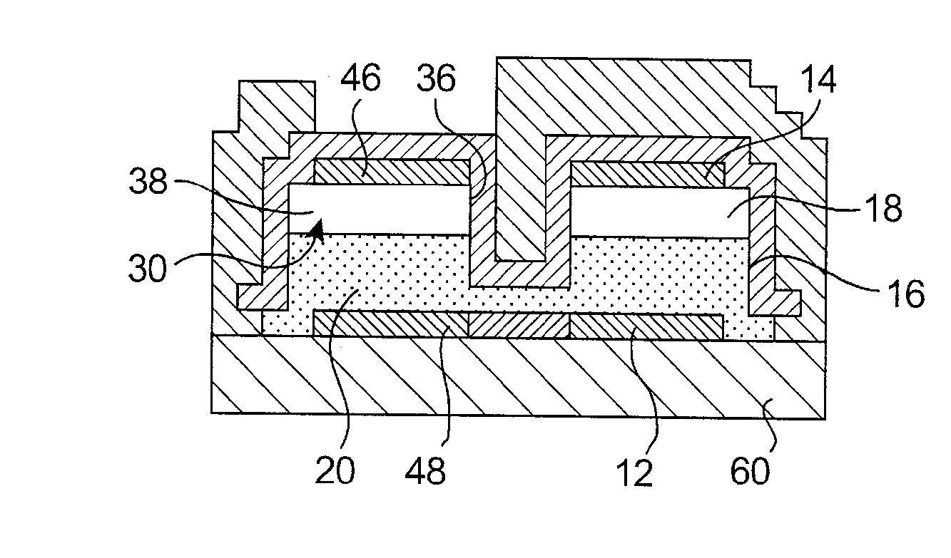
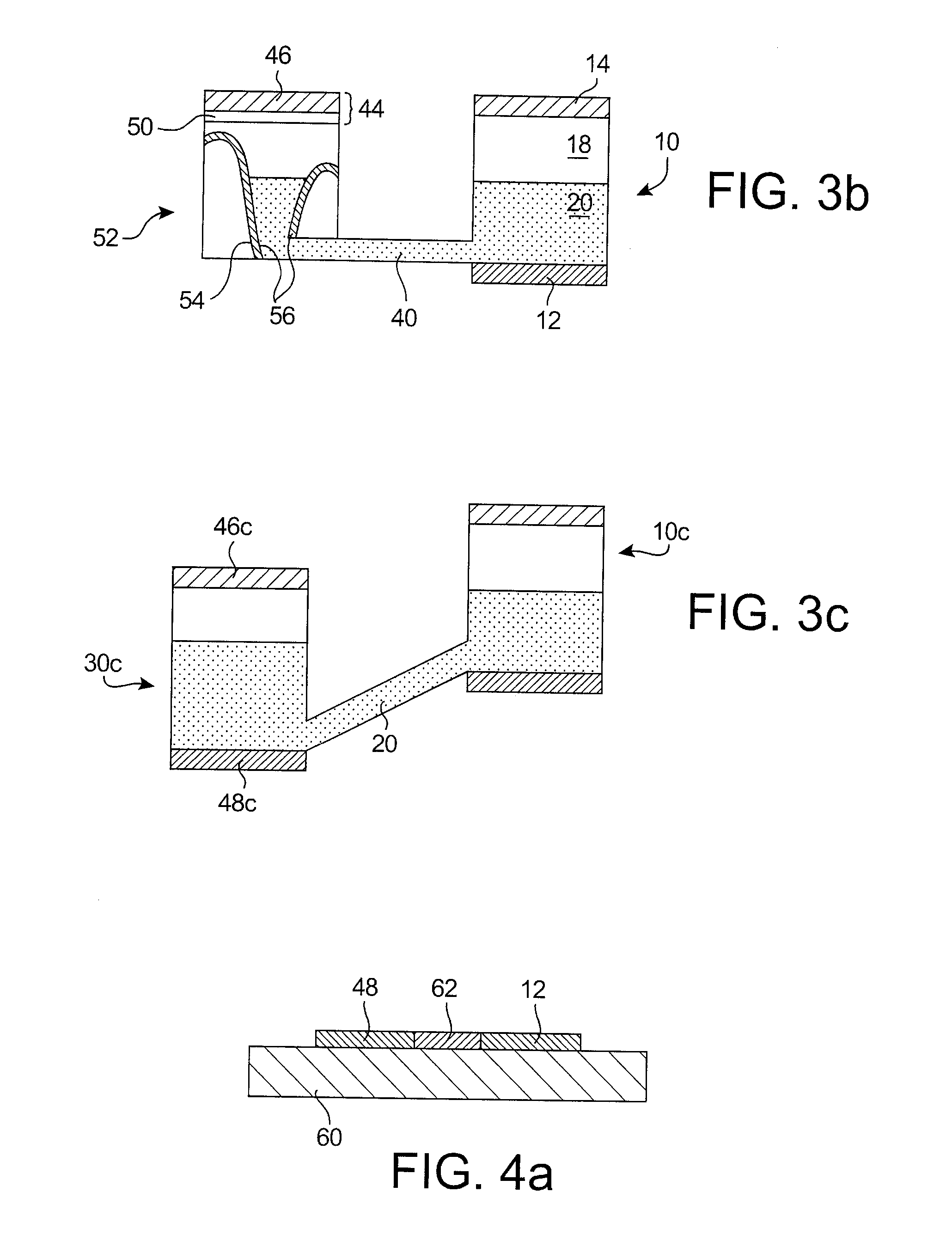
The variable capacitance (1) according to the invention is based on a novel principle: a dielectric fluid (20) is placed in the air gap constituted by two capacitor electrodes (12, 14), the fluid being able to be displaced in a direction and outside the cavity (10) formed between said two electrodes (12, 14). Advantageously, the dielectric fluid (20) is displaced according to the principle of communicating vessels, with the presence of a second cavity (30) in fluidic relation with the first cavity. Actuation electrodes (46, 48) in the second cavity (30) induce the deflection of a membrane (44) in order to modify the relative heights of fluidic liquid in the two cavities (10, 30).

Description

TECHNICAL FIELD [0001] The invention relates to the field of capacitor type electronic devices having a variable capacitance and, more particularly, to electromechanical Microsystems in which the capacitance is modulated by the variation in volume of a dielectric fluid between two electrodes. STATE OF THE PRIOR ART [0002] The development of increasingly smaller and efficient portable devices prompts the search for new components to perform new functionalities. Thus, in radiofrequency (RF) applications such as mobile telephony, portable computers, or any other communicating object, etc., Micro-Electro-Mechanical Systems (or MEMS) are credible alternatives to “conventional” microelectronic components due to their integration and their theoretical performance. [0003] In this context, MEMS devices in which the capacitance (electrical) is variable but having a low actuation voltage and a wide range of capacitance variation are sought. The field of RF imposes moreover a dissociation betwe...

Claims


Application Information

Patent Timeline
IPC IPC(8): H01G5/00
CPCY10T29/43H01G5/0132
Inventor CASSET, FABRICE
Owner COMMISSARIAT A LENERGIE ATOMIQUE ET AUX ENERGIES ALTERNATIVES
Learn More