
Motion Compensation Prediction Method and Motion Compensation Prediction Apparatus

a motion compensation and prediction method technology, applied in signal generators with optical-mechanical scanning, color televisions with bandwidth reduction, signal generators, etc., can solve the problems of heavy refinement processing in motion compensation prediction (taking a long time) and achieve the effect of reducing memory access and high speed of motion vector search

Inactive Publication Date: 2008-02-14
SONY CORP
View PDF14 Cites 46 Cited by
  • Summary
  • Abstract
  • Description
  • Claims
  • Application Information

AI Technical Summary

Benefits of technology

The present invention provides an image information encoding apparatus that can output image compressed information based on image encoding systems such as AVC, etc. The invention solves the problem of high speed of motion vector search and reduction in memory access. The invention is directed to a motion compensation prediction method and apparatus that can search motion vector by using a hierarchical search and determine reference image based on the search. The technical effects of the invention are improved speed and efficiency in image compression and motion compensation prediction.

Problems solved by technology

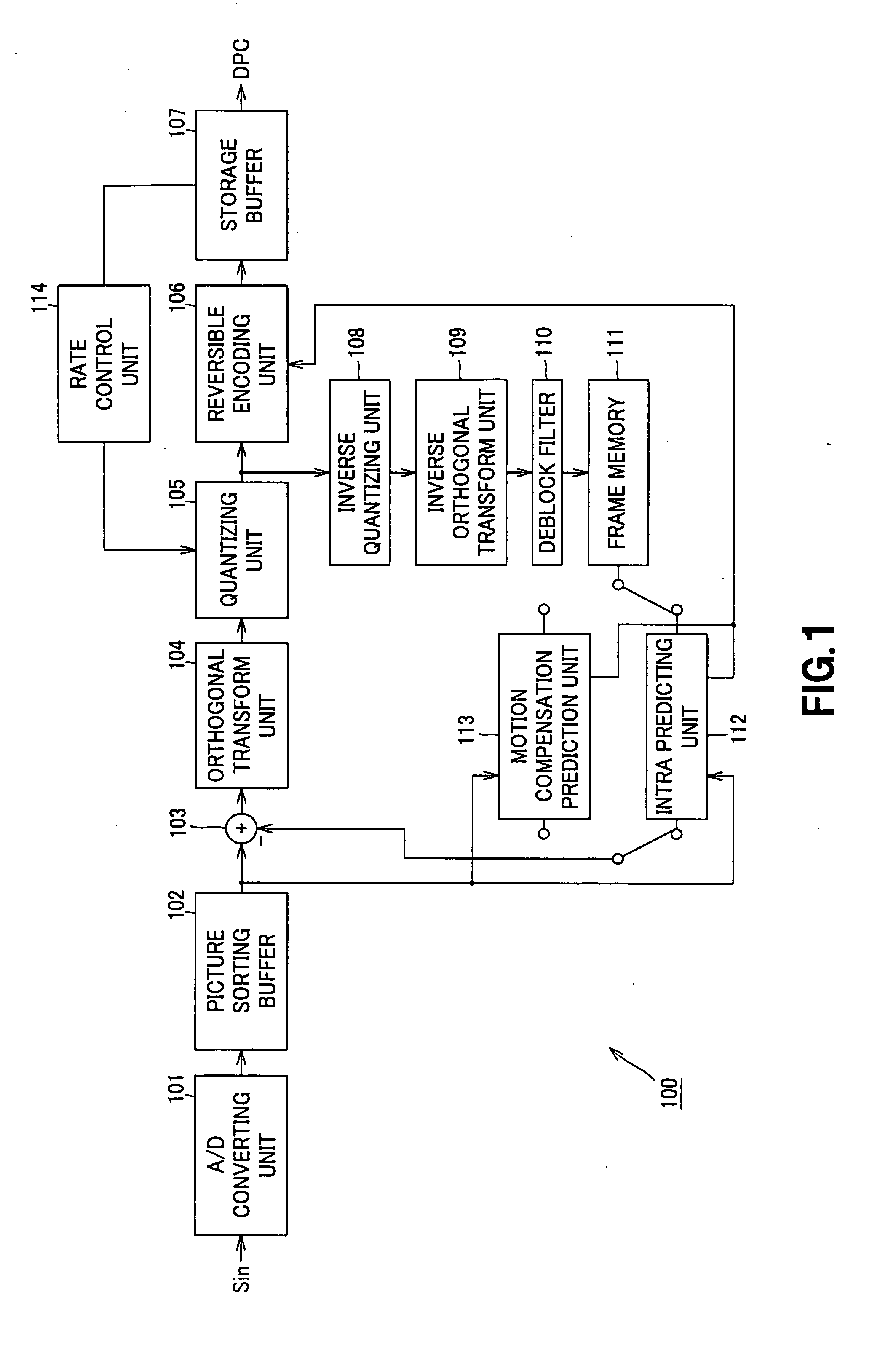
However, in the AVC encoding system, as previously described above, since multiple reference frame motion compensation, motion compensation (prediction) using variable block size and motion compensation of ¼ pixel accuracy are permissible, when the number of candidate reference frames is increased, the Refinement processing in the motion compensation prediction would be heavy (takes much time).

Method used


Image

  • Motion Compensation Prediction Method and Motion Compensation Prediction Apparatus
  • Motion Compensation Prediction Method and Motion Compensation Prediction Apparatus
  • Motion Compensation Prediction Method and Motion Compensation Prediction Apparatus

Examples


Embodiment Construction

[0053] Preferred embodiments of the present invention will now be explained in detail with reference to the attached drawings. It should be noted that the present invention is not limited to the following examples, but it is a matter of course that the present invention may be arbitrarily changed or modified within the gist which does not depart from the gist of the present invention.

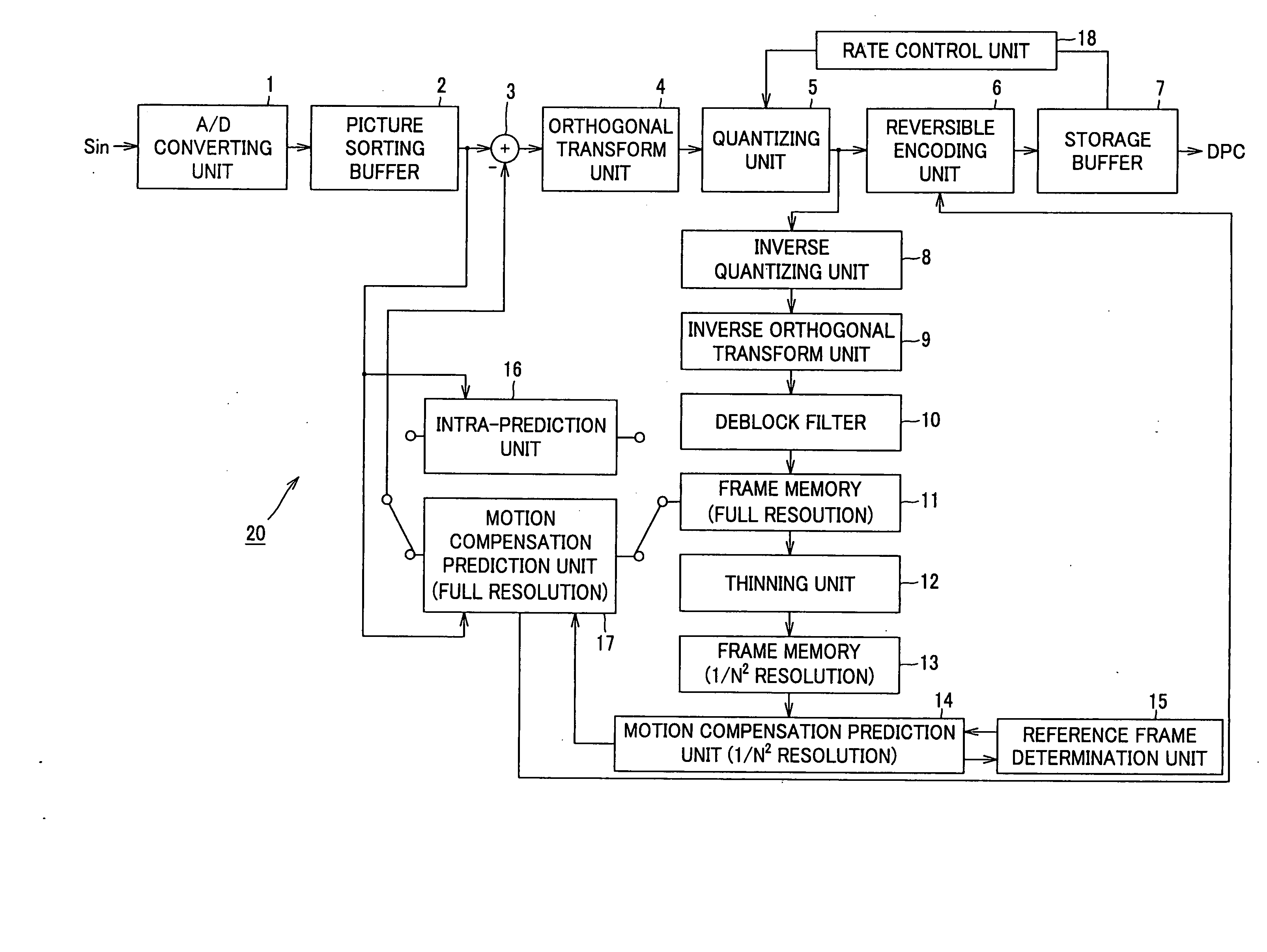
[0054] The present invention is applied to, e.g., an image information encoding apparatus 20 of the configuration as shown in FIG. 7.

[0055] Namely, the image information encoding apparatus 20 shown in FIG. 7 comprises an A / D converting unit 1 supplied with an image signal Sin serving as input, a picture sorting buffer 2 supplied with image data digitized by the A / D converting unit 1, an adder 3 supplied with image data which has been read out from the picture sorting buffer 2, an intra-predicting unit 16, a motion compensation prediction unit 17, an orthogonal transform unit 4 supplied with an output ...


PUM


Abstract

When motion vector is searched based on hierarchical search by designating any one of reference images of plural frames used every respective motion blocks, which have reference images of plural frames and are obtained by dividing an object frame image to be processed among successive frame images, a thinning unit (12) is operative to thin pixels of the motion compensation block having the largest pixel size caused to be uppermost layer among pixel sizes of the motion compensation block to thereby generate a contracted image of lower layer having a predetermined contraction factor; a reference frame determination unit (15) is operative to determine a contracted reference image on the contracted image; a motion compensation prediction unit (1 / N2 resolution) (15) is operative to search motion vector by using the contracted image thus generated to search; with respect to an image before contraction, motion compensation prediction unit (full resolution) (17) is operative to search motion vector and perform motion compensation prediction by using a predetermined retrieval range designated by motion vector which has been searched at the motion compensation prediction unit (1 / N2 resolution) (15).

Description

[0001] When motion vector is searched based on hierarchical search by designating any one of reference images of plural frames used every respective motion blocks, which have reference images of plural frames and are obtained by dividing an object frame image to be processed among successive frame images, a thinning unit (12) is operative to thin pixels of the motion compensation block having the largest pixel size caused to be uppermost layer among pixel sizes of the motion compensation block to thereby generate a contracted image of lower layer having a predetermined contraction factor; a reference frame determination unit (15) is operative to determine a contracted reference image on the contracted image; a motion compensation prediction unit (1 / N2 resolution) (14) is operative to search motion vector by using the contracted image thus generated to search; with respect to an image before contraction, motion compensation prediction unit (full resolution) (17) is operative to searc...

Claims


Application Information

Patent Timeline
Patent Type & Authority Applications(United States)
IPC IPC(8): H04N7/12H04N19/105H04N19/50H04N19/134H04N19/137H04N19/147H04N19/174H04N19/196H04N19/503H04N19/51H04N19/53H04N19/553H04N19/567H04N19/57H04N19/59H04N19/593H04N19/60H04N19/61H04N19/625H04N19/82H04N19/90H04N19/91
CPCH04N19/51H04N19/567H04N19/53H04N19/82H04N19/176
Inventor TSUCHIYA, TOSHIHARUWADA, TORUSATO, KAZUSHIYAMADA, MAKOTO
Owner SONY CORP
Learn More