Steerable Multistage Collimation for Radiographic Imaging

a radiographic imaging and multi-stage technology, applied in the field of radiographic imaging, can solve the problems of significant radiation emission from the object being irradiated, negative influence on the resolution and sensitivity of the imaging system, and typical collimators are not able to adequately filter beams, etc., to achieve the effect of reducing scatter and large area imagining

Inactive Publication Date: 2008-02-14
3M IMTEC
View PDF6 Cites 2 Cited by
  • Summary
  • Abstract
  • Description
  • Claims
  • Application Information

AI Technical Summary

Benefits of technology

[0007] The present invention solves this and other problems by providing a movable multistage collimation system. Multiple collimators are used to successively trim the radiation beam to match the detector plate while simultaneously eliminating scatter from previous stages. This allows large area imagining with reduced scatter.
[0008] A preferred embodiment of the present invention uses a steerable beam that is produced by multiple moving collimator stages used with fixed collimation stages. The beam is reduced to cover only the active area of the detector in any position. This decreases the amount of scatter produced by the object being irradiated.
[0009] Another preferred embodiment of the present invention moves the movable collimator stages in horizontal and vertical directions. This further allows the beam to be focused on specific portions of the object being imaged to match the movement of the detector plate.

Problems solved by technology

One problem with radiographic imaging, such as computed tomography, X-rays and other types of radiation point systems is scatter.
Scatter detected by the detector during the imaging process negatively affects the resolution and sensitivity of the imaging system.
A problem arises when large area imaging is conducted as the object being irradiated will reflect beams, give off radiation during the process, and / or reflect off the collimator itself.
Typical collimators are not able to adequately filter beams when used with large area imaging.
However, there still may be significant radiation emitting from the object being irradiated.
This not only affects the resolution and sensitivity of the image but may also damage the detector as well.
This is particularly a problem with large objects.
Thus a problem exists with the prior radiographic imaging systems particularly when large area imaging is performed.

Method used


Image

  • Steerable Multistage Collimation for Radiographic Imaging
  • Steerable Multistage Collimation for Radiographic Imaging
  • Steerable Multistage Collimation for Radiographic Imaging

Examples


Embodiment Construction

[0016] The present invention provides systems and process for minimizing scatter in radiographic systems. Preferred embodiments of these systems and processes are discussed below. It is to be expressly understood that this descriptive embodiment is provided for explanatory purposes only and is not meant to limit the scope of the claimed invention. Other types and uses of the systems and processes are also considered to be within the scope of the present invention.

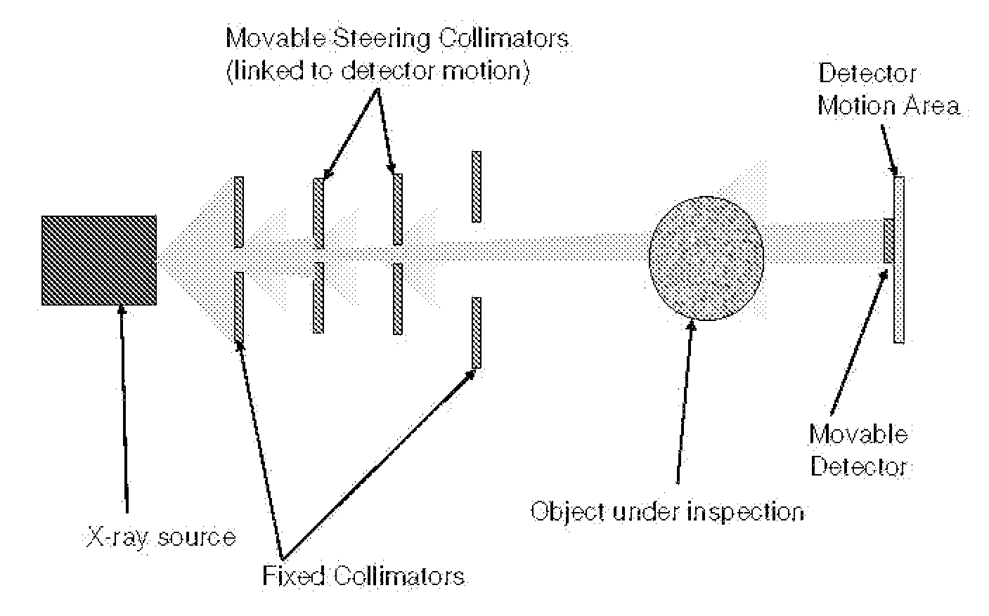
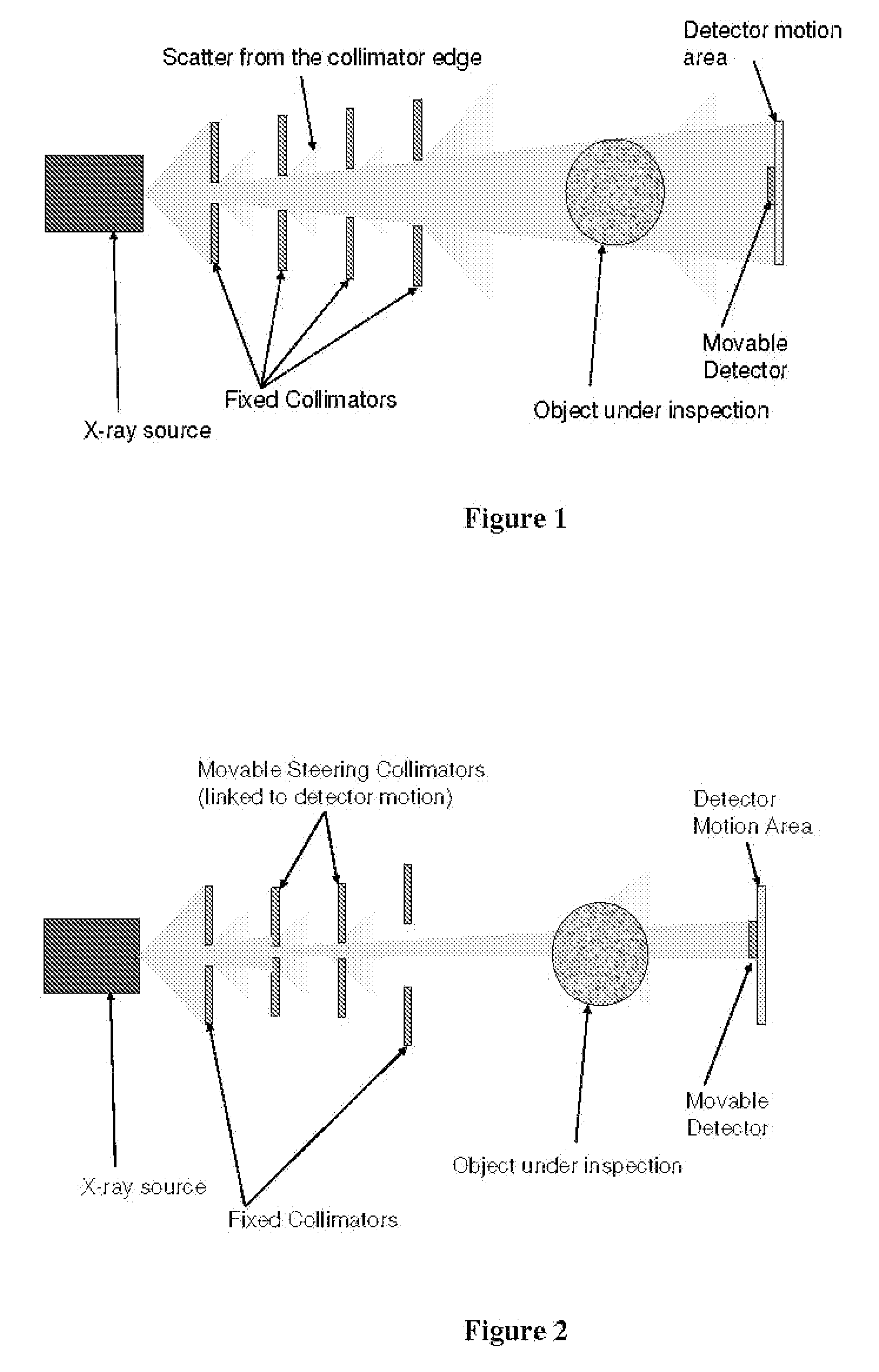
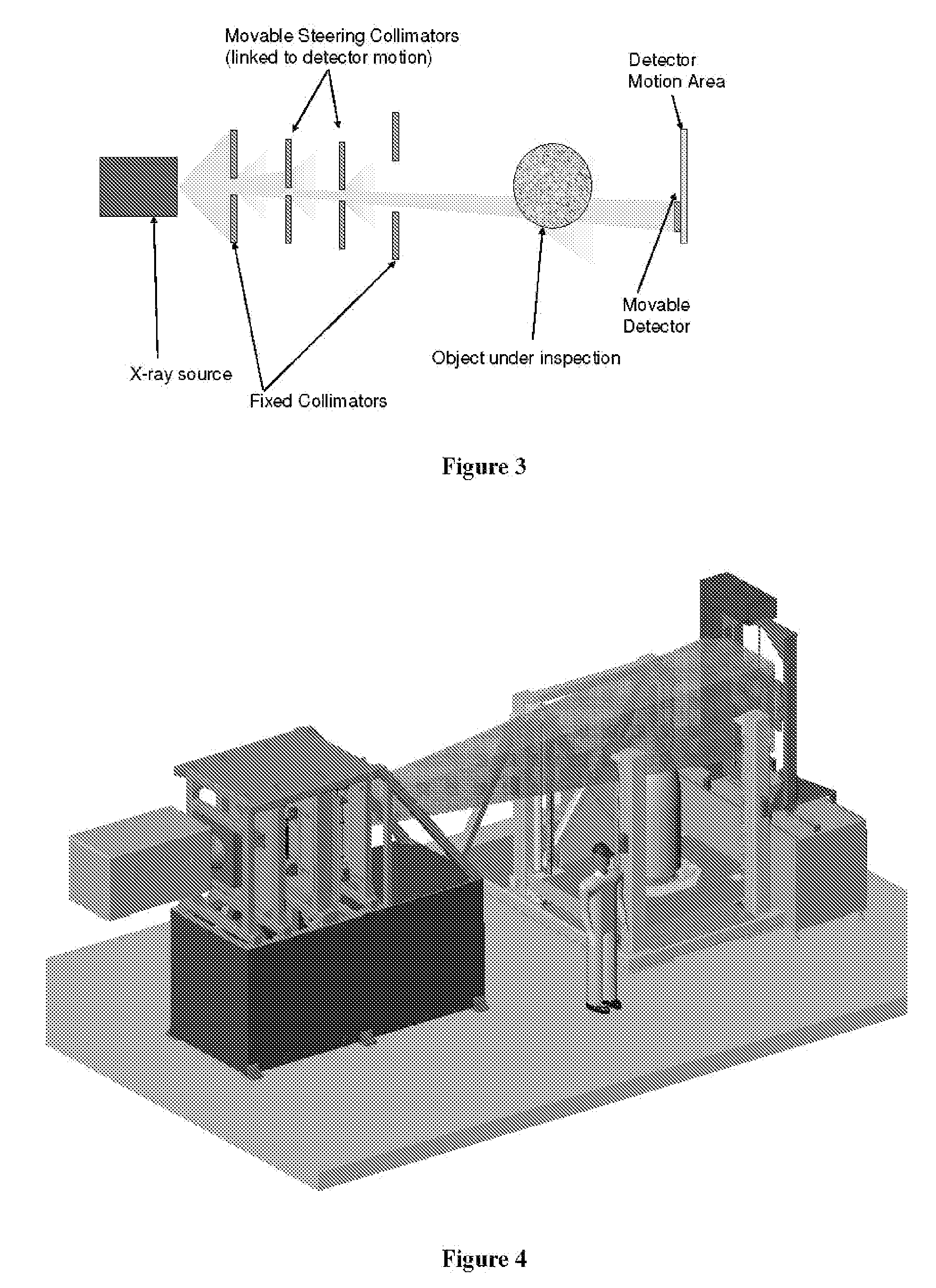
[0017] The present invention includes a novel method for reducing scatter in radiographic imaging systems while permitting large area imaging. Multiple collimators are used to successively trim the radiation beam to match the detector plate while simultaneously eliminating scatter from the previous stages. The movable collimation stages, in conjunction with nonmoving scatter reduction stages, trim the beam to match the detector area. For larger part imaging, the detector may move. The present invention allows the collimato...


PUM


Abstract

A system for reducing scatter in radiographic imaging systems while permitting large area imaging. Multiple collimators are used to successively trim the radiation beam to match the detector plate while simultaneously eliminating scatter from the previous stages. The movable collimation stages, in conjunction with nonmoving scatter reduction stages, trim the beam to match the detector area. For larger part imaging, the detector may move. The present invention allows the collimators to move with the detector to steer the collimated beam onto only the active area of the detector.

Description

RELATED APPLICATIONS [0001] This application is continuation of Ser. No. 11 / 464,480, filed on Aug. 14, 2006 which is a continuation of Ser. No. 11 / 277,611, filed on Mar. 27, 2006 which claims benefit of provisional application 60 / 594,308.FIELD OF THE INVENTION [0002] This invention relates to the field of radiographic imaging and particularly to the field of reducing scatter in radiographic imaging. BACKGROUND OF THE INVENTION [0003] One problem with radiographic imaging, such as computed tomography, X-rays and other types of radiation point systems is scatter. Scatter is defined as secondary radiation resulting from deflected radiation, from radiation generated from the object being imaged, radiation that travels along non-direct paths to the detector or other secondary radiation that is detected during the imaging process. Scatter detected by the detector during the imaging process negatively affects the resolution and sensitivity of the imaging system. [0004] One attempt to solve...

Claims


Application Information

Patent Timeline
Patent Type & Authority Applications(United States)
IPC IPC(8): G21K1/02
CPCG21K1/025
Inventor DAVIS, ANTHONY
Owner 3M IMTEC
Why Eureka
Try Eureka