Block noise removal device

a block noise and noise removal technology, applied in the direction of instruments, electrical appliances, computing, etc., can solve the problems of quantization noise and smoothing processing cannot achieve the effect of noise removal, and achieve the effect of removing block noise reliably and without degrading image quality

Inactive Publication Date: 2008-02-14
PIONEER CORP
View PDF13 Cites 36 Cited by
  • Summary
  • Abstract
  • Description
  • Claims
  • Application Information

AI Technical Summary

Benefits of technology

[0007] It is one object of the present invention to provide a block noise removal device that can reliably remove b

Problems solved by technology

However, because some values are omitted, the quantization noise is generated.
However, such smoothing processing cannot ac

Method used


Image

  • Block noise removal device
  • Block noise removal device
  • Block noise removal device

Examples


Embodiment Construction

[0023] An embodiment of the present invention will be described below with reference to the appended drawings.

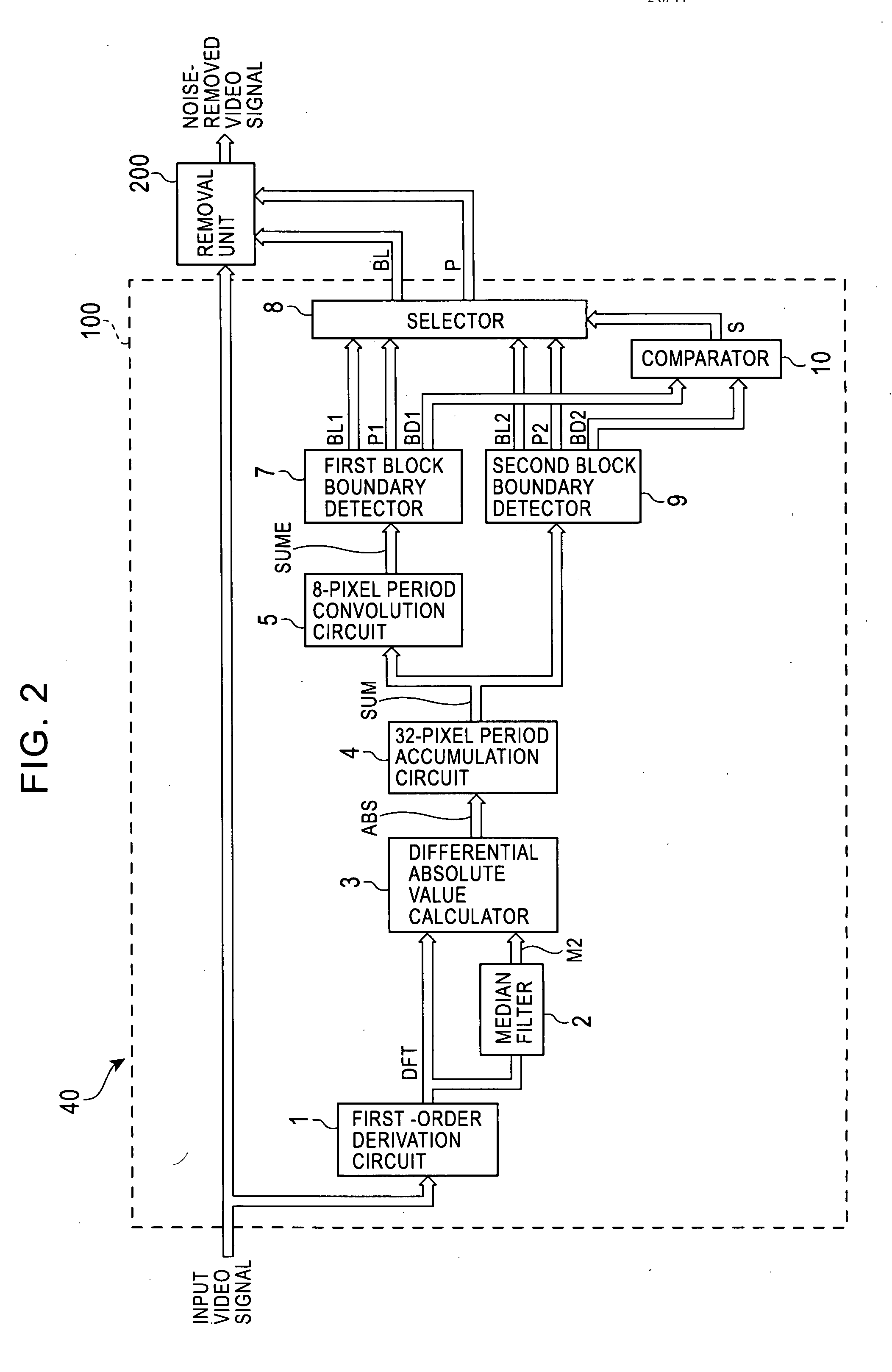
[0024] Referring to FIG. 2, the configuration of a block noise removal device 40 according to one embodiment of the present invention will be described.

[0025] As shown in FIG. 2, the block noise removal device 40 includes a detection unit 100 and a removal unit 200. The detection unit 100 detects a block noise from (in) an input video signal. The removal unit 200 removes the block noise generated in the input video signal according to the block noise detection result.

[0026] The detection unit 100 has a first-order derivation circuit 1, a median filter 2, a differential absolute value computation circuit 3, a 32-pixel period accumulation circuit 4, an 8-pixel period convolution circuit 5, a first block boundary detection circuit 7, a selector 8, a second block boundary detection circuit 9, and a comparator 10.

[0027] The first-order derivation circuit 1 calculates a signal...


PUM


Abstract

A block noise removal device calculates a block boundary correction value. This correction value indicates a correction amount for a pixel sample value immediately before a block boundary position and a correction amount for a pixel sample value immediately after the block boundary position for each block boundary position in a pixel sample value sequence. Each pixel sample value represents a level of each pixel in a video signal. The block noise removal device obtains the block boundary correction value based on at least two consecutive pixel sample values immediately before the block boundary position and at least two consecutive pixel sample values immediately after the block boundary position. The block noise removal device then generates a block noise correction signal representing a correction amount for the pixel sample values corresponding to respective pixels in the pixel block is generated by performing interpolation computations based on the block boundary correction value found for each two adjacent block boundary positions. The block noise removal device adds the block noise correction signal to the video signal to produce a noise-removed video signal from which block noise has been removed.

Description

BACKGROUND OF THE INVENTION [0001] 1. Field of the Invention [0002] The present invention relates to a block noise removal device that removes block noise generated in decoding information data that are compression coded for each of blocks of the information data. [0003] 2. Description of the Related Art [0004] Compression coding that employs a MPEG (Moving Picture Expert Group) method is often used for reducing the volume of information when video or audio signals are transmitted and / or recorded. With the MPEG coding processing, discrete cosine transformation (referred to hereinbelow as DCT) is implemented for each two-dimensional unit block with respect to a video signal, so as to obtain DCT coefficients of each frequency region, and then the volume of information is compressed by performing quantization processing. The larger is the quantization step used for the quantization processing, the higher is the compression ratio. However, because some values are omitted, the quantizati...

Claims


Application Information

Patent Timeline
IPC IPC(8): G06K9/40
CPCH04N19/176H04N19/61H04N19/14H04N19/59H04N19/42H04N19/86H04N19/182
Inventor OKUMICHI, KENJIHONDA, HIROFUMI
Owner PIONEER CORP
Why Eureka
Try Eureka