
Method and apparatus for managing and transmitting fine granularity services

a technology of fine granularity and transmission method, applied in the field of optical communication technologies, can solve the problems of poor recovery performance, inacceptable by equipment manufacturers and network operators, and performance problems, and achieve the effects of ensuring the continuity of services, saving storage space of nodes, and increasing bandwidth utilization ra

Active Publication Date: 2008-02-14
HUAWEI TECH CO LTD
View PDF12 Cites 4 Cited by
  • Summary
  • Abstract
  • Description
  • Claims
  • Application Information

AI Technical Summary

Benefits of technology

The present invention provides a method and apparatus for transmitting fine granularity services over a network. The invention aims to improve network bandwidth utilization and ensure the recovery performance of fine granularity services. The method involves increasing the bandwidth of an existing LSP (Service Function Path) that controls a fine granularity service when the new fine granularity service has the same source and destination nodes as the existing LSP. The method also includes transmitting a new fine granularity service along an existing LSP if the source and destination nodes are not identical. The invention also provides a process for integrating fine granularity services into a coarse granularity service when the number of fine granularity services exceeds a certain threshold. Additionally, the invention includes a re-routing process to control fine granularity services when there is a failure in the existing LSP. The technical effects of the invention include improved network bandwidth utilization, ensured recovery performance of fine granularity services, and improved reliability of the network.

Problems solved by technology

However, as the bandwidth of one VC4 is enough for 63 VC12 LSPs, the number of VC12 LSPs grows so huge that varieties of problems concerning performance emerge, which are unacceptable by equipment manufacturers and network operators.
For example, provided there are 48 services with VC4 bandwidth over an optical fiber and each VC4 contains 63 VC12 LSPs, when the optical fiber is interrupted, there will be 48*63 LSPs initiating re-routing processes, which takes long time to recover and thus leads to poor recovery performance; furthermore, in a node with 40 Gbps lower order cross-connection capability, 4*64*63 / 2=8064 VC12 LSPs may be established, which will occupy a large storage space of the node and lead to the shortage of the storage space.
However, in the case that an end-to-end tunnel is established, a dedicated VC4 tunnel will be occupied even there is only one VC12 service or just a few VC12 services transmitted through the tunnel, which results in a very low bandwidth utilization rate.
In the case that a segment tunnel is established, i.e., VC4 tunnels are established in advance between every two nodes and VC12 services are loaded on these tunnel segments, as every node is the source node and the destination node of an LSP tunnel, when there is a failure in one of the nodes or the optical fibers on both sides of a node are interrupted at the same time, the tunnel LSP cannot perform a re-routing process, hence the VC12 services cannot be effectively protected.

Method used


Image

  • Method and apparatus for managing and transmitting fine granularity services
  • Method and apparatus for managing and transmitting fine granularity services
  • Method and apparatus for managing and transmitting fine granularity services

Examples


first embodiment

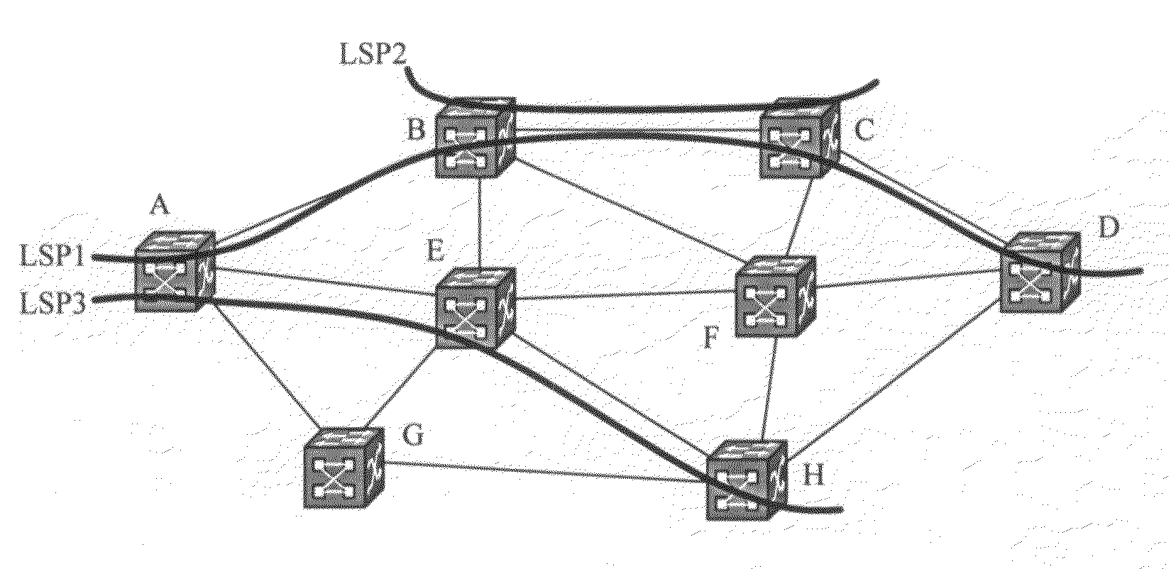
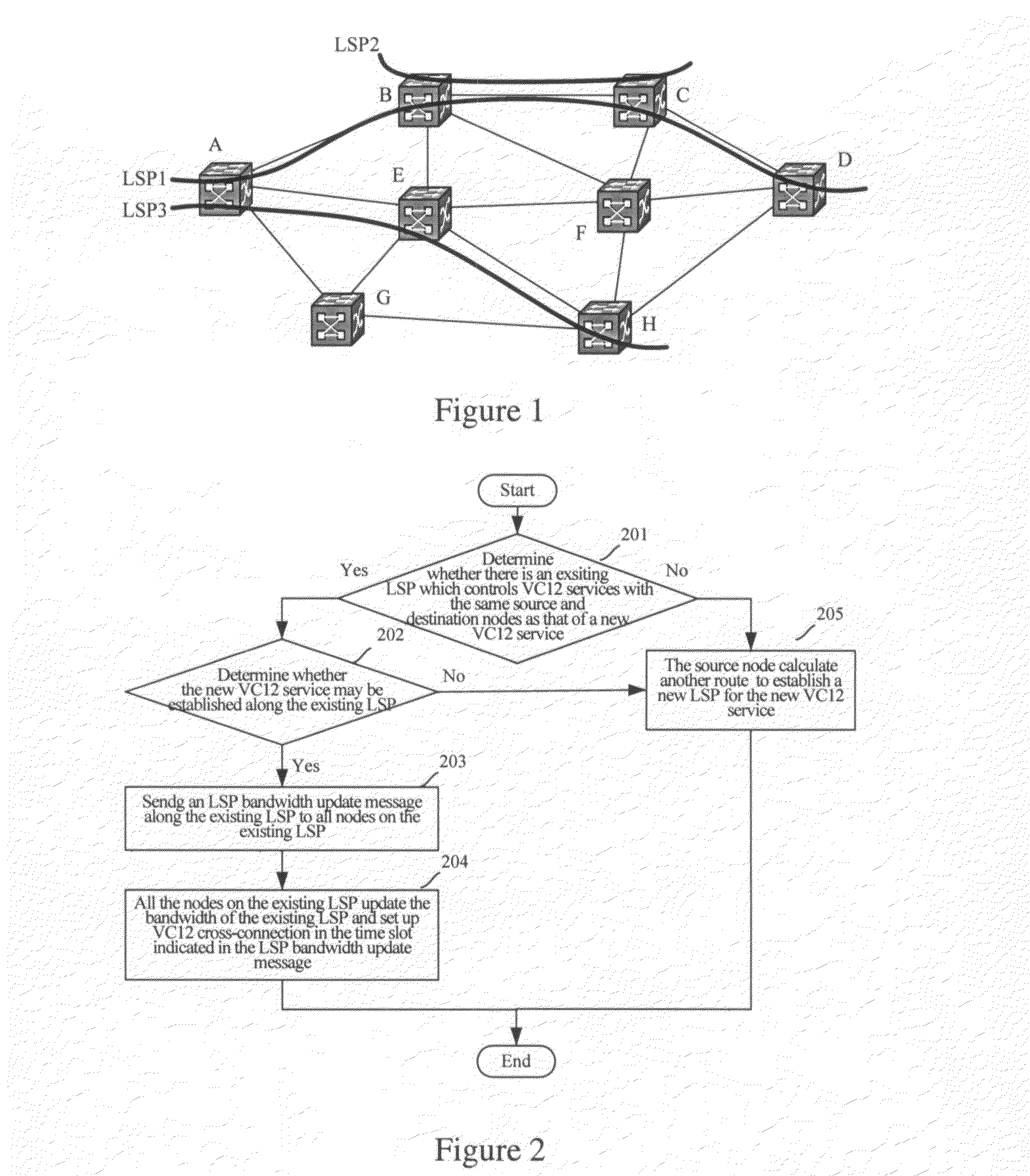
[0060]In order to solve the problem in the prior art, the present invention provides a method for managing and transmitting VC12 services, including:

[0061]1) establishing one LSP for a group of VC12 services (less than or equal to 63 services) with the same source node and destination node, and transmitting the VC12 services through the same path;

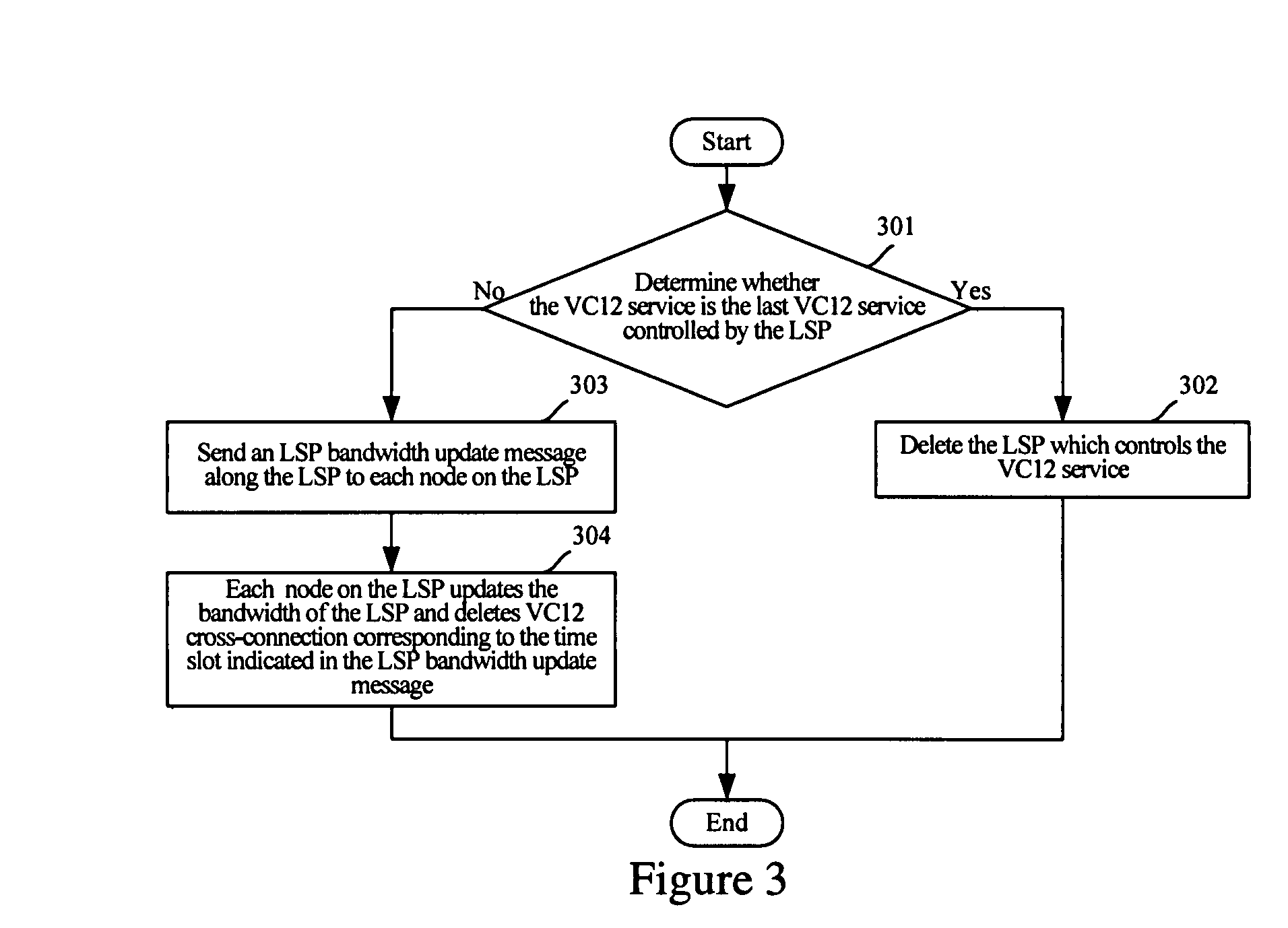
[0062]2) establishing an LSP for controlling the first VC12 service to be established, updating the bandwidth of the LSP when a VC12 service is established or deleted, and deleting the LSP when the last VC12 service controlled by the LSP is deleted;

[0063]3) re-routing all the VC12 services controlled by the LSP at the same time (or in batches) to another path (or paths) upon there is a failure on the path, e.g., a optical fiber broken;

[0064]4) integrating VC12 services into a VC4 tunnel through resource integration when the number of VC12 services of same group controlled by same LSP reaches a predetermined value (e.g., 48), so as to save t...

third embodiment

[0095]The failure recovery process of VC12 service is explained hereafter with reference to accompanying drawings and the present invention.

[0096]FIG. 5A shows an LSP in the normal condition. As shown in FIG. 5A, an LSP controlling 30 VC12 services is established between Node A and Node D in a network. The LSP passes through Node B and Node C.

[0097]FIG. 5B is a schematic drawing illustrating the LSP after a re-routing process of VC12 services when the optical fiber breaks between Node B and Node C shown in FIG. 5A. As shown in FIG. 5B, when the optical fiber breaks between Node B and Node C, an alert message triggers the LSP re-routing process, and another LSP, between Node A and Node D, passing through Node E and Node F, is established. In the re-routing process, all the VC12 services controlled by the LSP are re-routed at the same time and transmitted along the same path, VC12 cross-connection controlled by the LSP is issued to all nodes on the path at the same time and a verifica...


PUM


Abstract

Embodiments of the present invention provide a method and an apparatus for managing and transmitting fine granularity services. The method includes: increasing the bandwidth of an existing LSP which controls a fine granularity service with the same granularity as that of a new fine granularity service to be established, upon determining that the new fine granularity service shares the same source node and destination node with the existing LSP; and transmitting the new fine granularity service with the increased bandwidth of the existing LSP. The bandwidth utilization rate of optical networks can be obviously increased when transmitting fine granularity services in accordance with the embodiments of the present invention; furthermore, the storage space of each node through which the LSP passes is saved and the recovery performance of fine granularity services is guaranteed.

Description

FIELD OF THE INVENTION[0001]The present invention relates to optical communication technologies, and particularly, to a method and an apparatus for managing and transmitting fine granularity services.BACKGROUND OF THE INVENTION[0002]An Automatically Switched Optical Network (ASON) is a type of dynamically and automatically switched transport network. It is a new generation of optical networks, wherein a service request is initiated dynamically by users; a path is calculated and selected automatically by a network element; and the setup, restoration, clearance of a connection are controlled by signaling; moreover switching and transporting are integrated.[0003]An ASON includes two layers: a control plane and a transport plane. The function of the control plane includes collecting and distributing the network topology of the ASON to form a “network map” representing the accurate network topology, calculating a viable path with some routing algorithms by use of the “network map”, and e...

Claims


Application Information

Patent Timeline
Patent Type & Authority Applications(United States)
IPC IPC(8): H04J14/00H04L12/54
CPCH04J2203/0053H04J2203/006H04Q2011/0077H04L41/0896H04L45/50H04L12/5695H04L47/70
Inventor SHI, XINGHUA
Owner HUAWEI TECH CO LTD
Learn More