Rock bolt

a technology of bolts and bolts, applied in the field of rock bolts, can solve the problems of increasing the cost of installing rock bolts, requiring time and a significant amount of labor, and consuming the conventional procedure for installing rock bolts

Inactive Publication Date: 2008-02-14
FCI HLDG DELAWARE
View PDF10 Cites 46 Cited by
  • Summary
  • Abstract
  • Description
  • Claims
  • Application Information

AI Technical Summary

Benefits of technology

[0015] In an alternative embodiment, the drill bit is mounted by the chuck of the mechanical anchoring arrangement. The chuck in this embodiment includes a recess within which is seated the end of the rock bolt, for relative axial motion with respect to the chuck. A stop on the end of the rock bolt prevents the chuck from moving off the rock bolt during drilling.

Problems solved by technology

The conventional procedure for installing rock bolts can be relatively time consuming in the context of efficient mine operation.
It requires a number of separate tasks (affixing the drill steel, drilling the borehole, removing the drill steel, inserting the resin and rock bolt, securing the rock bolt) which require time and a significant amount of labour.
In a mining situation, where it is important that mining shafts, passageways, etc be created quickly (as this directly affects the economic operation of the mine), this is a disadvantage.
Further, the drill steel and drill bit are consumables which add to the cost of installing rock bolts.
Whilst self drilling rock bolts have the advantage of speed of application, grouting can be difficult and there are no provisions for any point anchoring mechanism to firmly secure the rock bolt.

Method used


Image

  • Rock bolt
  • Rock bolt
  • Rock bolt

Examples


first embodiment

[0029] the present invention will now be described with reference to FIGS. 1 to 3.

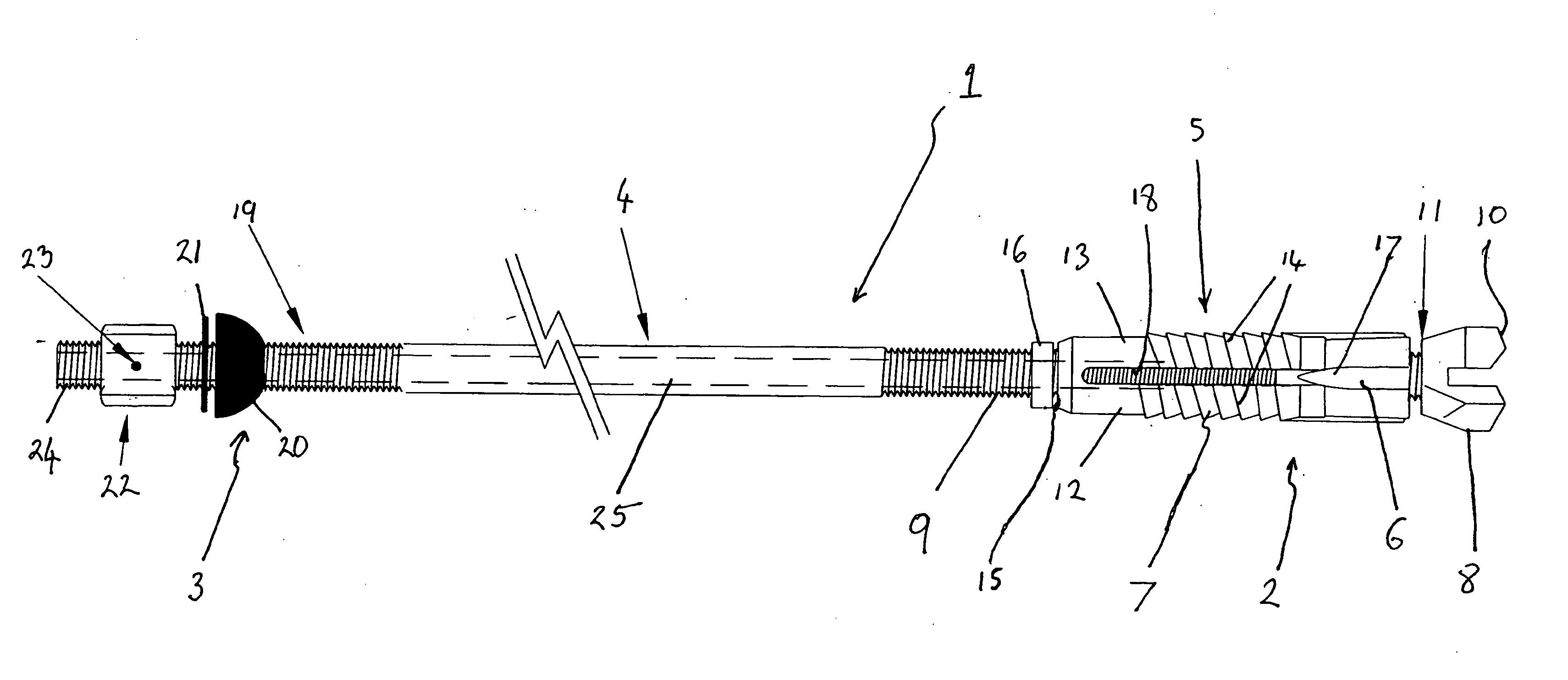
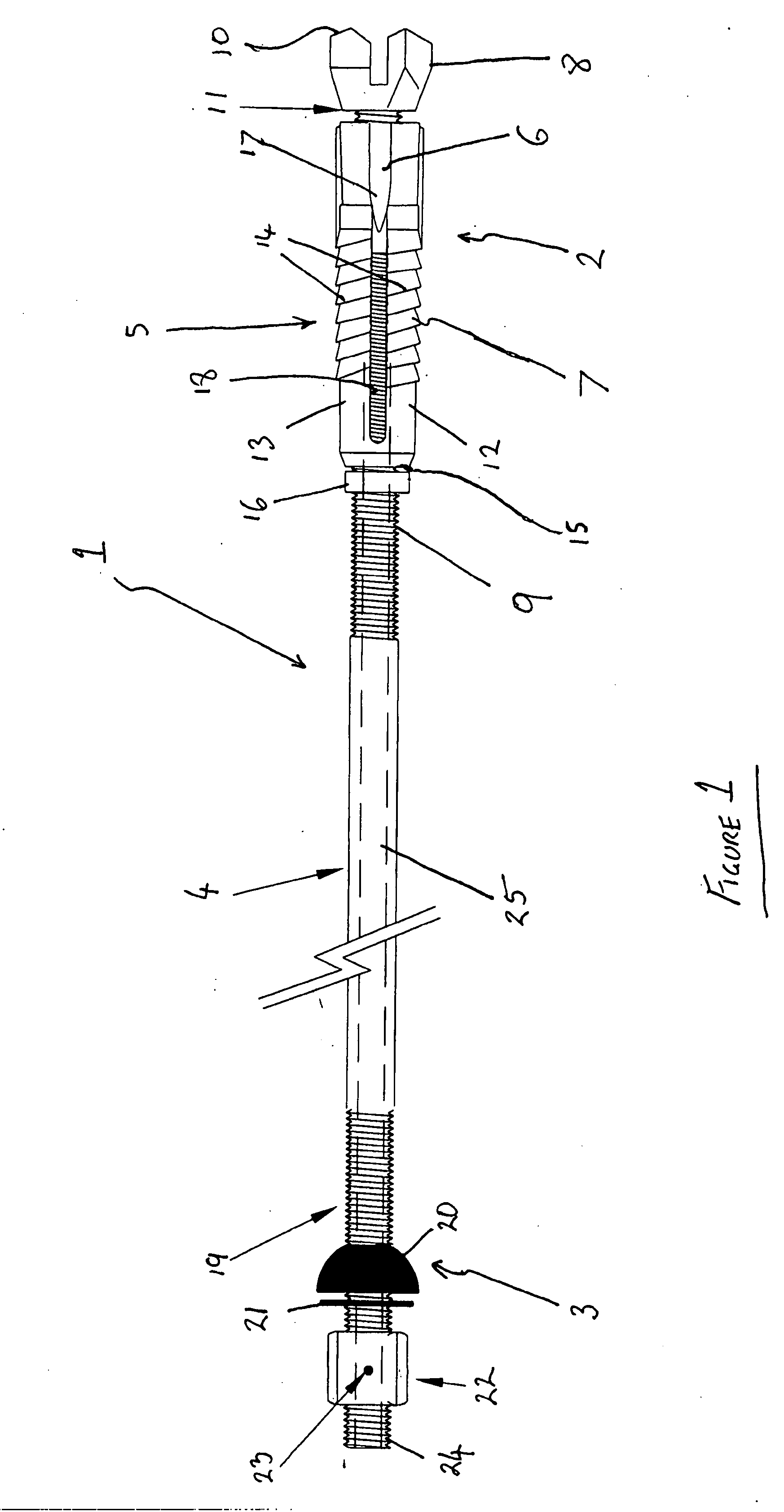
[0030] A rock bolt, generally designated by reference numeral 1 includes a distal, head end 2, and a proximal, tail end 3. A shank 4 extends between the head end 2 and tail end 3. The head end 2 includes a mechanical anchoring arrangement 5 which, in this example embodiment, includes a co-operating chuck 6 and expansion shell 7. The head end 2 is also provided with a drill bit 8 to enable self drilling. In this example embodiment, the drill bit 8 is mounted at the distal end of the rock bolt 1.

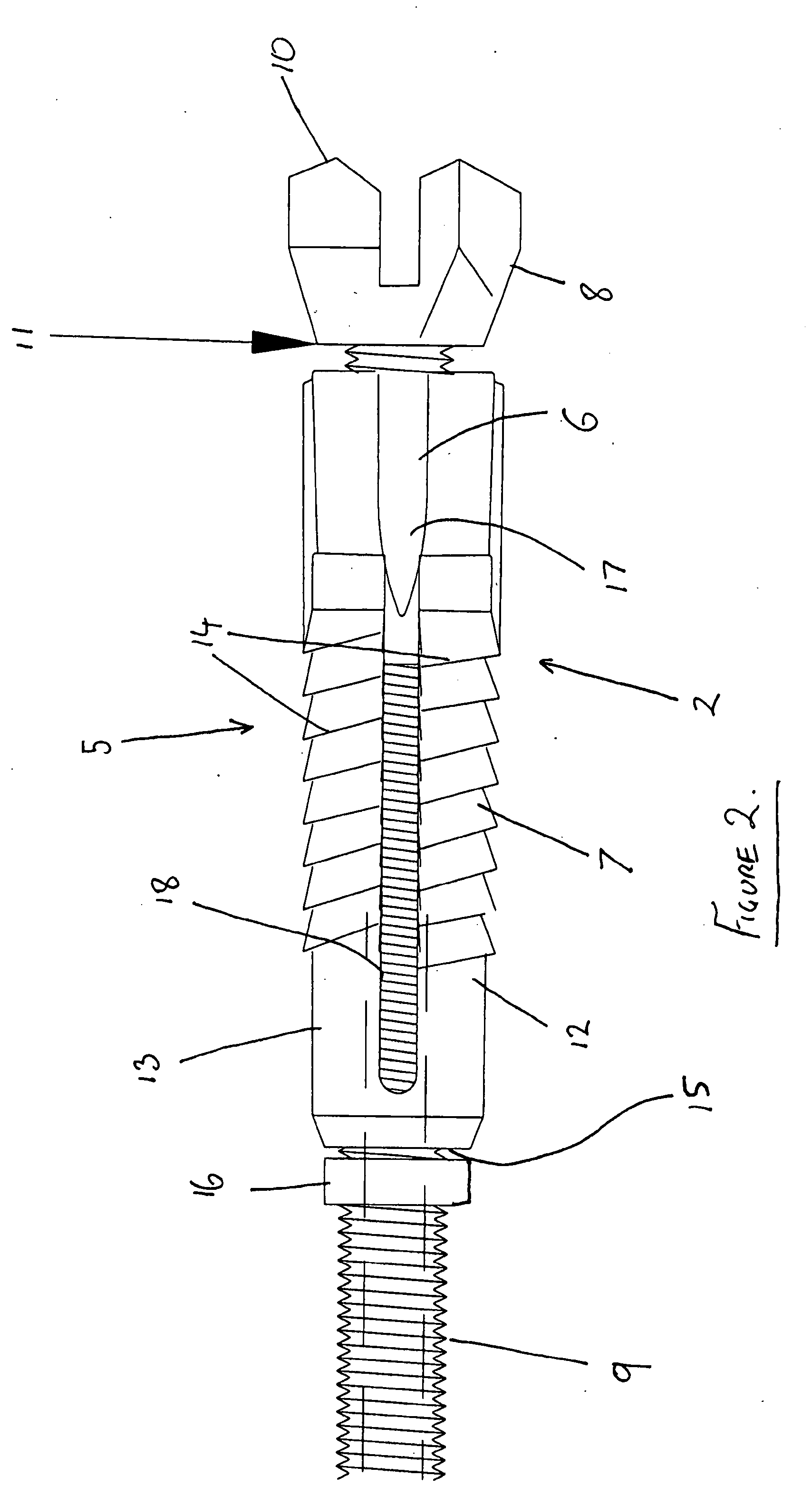
[0031] The mechanical anchoring arrangement 5 will now be described in more detail. Towards the head end 2, a shank 4 of rock bolt 1 is threaded with screw threads 9. The threaded portion 9 extends up to the drill bit 8. The drill bit 8 comprises a drilling tip 10 at the distal end of the rock bolt and a base forming a stop 11 where the threaded portion 9 meets the drill bit 8.

[0032] The mechanical anchoring ar...


PUM


Abstract

The present invention relates to rock bolts which may be used in mining applications. The rock bolt of this invention includes a mechanical anchoring arrangement to facilitate retaining the rock bolt in a borehole, and also a drill bit to enable self drilling of the rock bolt. Rotation of the rock bolt about an axis of the rock bolt in a first direction causes the drill bit to drill into rock and to create a borehole to receive the rock bolt. Subsequently, rotation in the opposite direction actuates a mechanical anchoring arrangement to anchor rock bolt.

Description

FIELD OF THE INVENTION [0001] The present invention relates to a rock bolt and particularly, but not exclusively, to rock bolts which may be used in mining applications. BACKGROUND OF THE INVENTION [0002] Rock bolts for supporting structures e.g. roofs of passageways in mines are well known. There are many different types of rock bolts. A rock bolt generally consists of an elongate shank (length will generally depend upon the material which the rock bolt is intended to secure) having a distal end (the end which in use is fixed furthest within the rock), or “head end”, and a proximal end (the end, in use, which is closest to the surface of a rock and, in many cases, may actually project from the rock surface), or “tail end”. [0003] Rock bolts are fixed in elongate boreholes (not much wider or even slightly less in width than the rock bolt) which is drilled in the rock. In use, a bearing plate is secured at the tail end of a rock bolt fast against the rock surface. The rock bolt and b...

Claims


Application Information

Patent Timeline
Patent Type & Authority Applications(United States)
IPC IPC(8): E21D20/02E21D21/00
CPCE21D21/0046E21D2021/0053E21D21/008E21D21/0053
Inventor CRAIG, PETER HAROLD
Owner FCI HLDG DELAWARE
Why Eureka
Try Eureka