Sector-Divided Turbine Assembly With Axial Piston Variable-Geometry Mechanism

a variable geometry and sector-divided technology, applied in the field of turbines, can solve the problems of compromising the benefits of sector division and variable geometry each

Inactive Publication Date: 2008-02-14
HONEYWELL INT INC
View PDF5 Cites 33 Cited by
  • Summary
  • Abstract
  • Description
  • Claims
  • Application Information

AI Technical Summary

Problems solved by technology

In known prior turbochargers having sector division and variable geometry, the full benefits of sector division generally have not been achieved; in fact, the benefits of sector division and variable geometry each have been compromised when such integration has been attempted.

Method used


Image

  • Sector-Divided Turbine Assembly With Axial Piston Variable-Geometry Mechanism
  • Sector-Divided Turbine Assembly With Axial Piston Variable-Geometry Mechanism
  • Sector-Divided Turbine Assembly With Axial Piston Variable-Geometry Mechanism

Examples


Embodiment Construction

[0019]The present inventions now will be described more fully hereinafter with reference to the accompanying drawings, in which some, but not all embodiments of the invention are shown. Indeed, these inventions may be embodied in many different forms and should not be construed as limited to the embodiments set forth herein; rather, these embodiments are provided so that this disclosure will satisfy applicable legal requirements. Like numbers refer to like elements throughout.

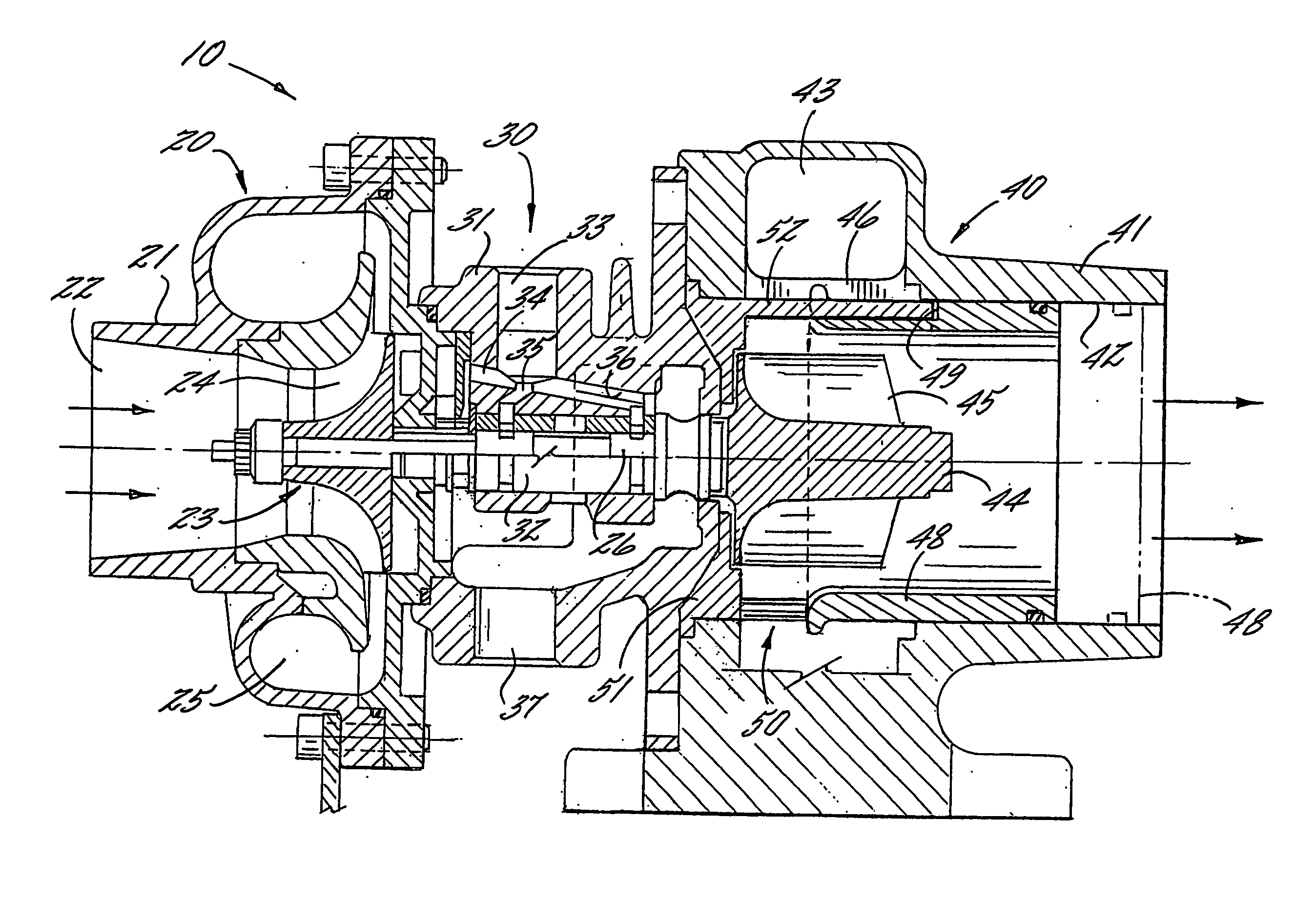
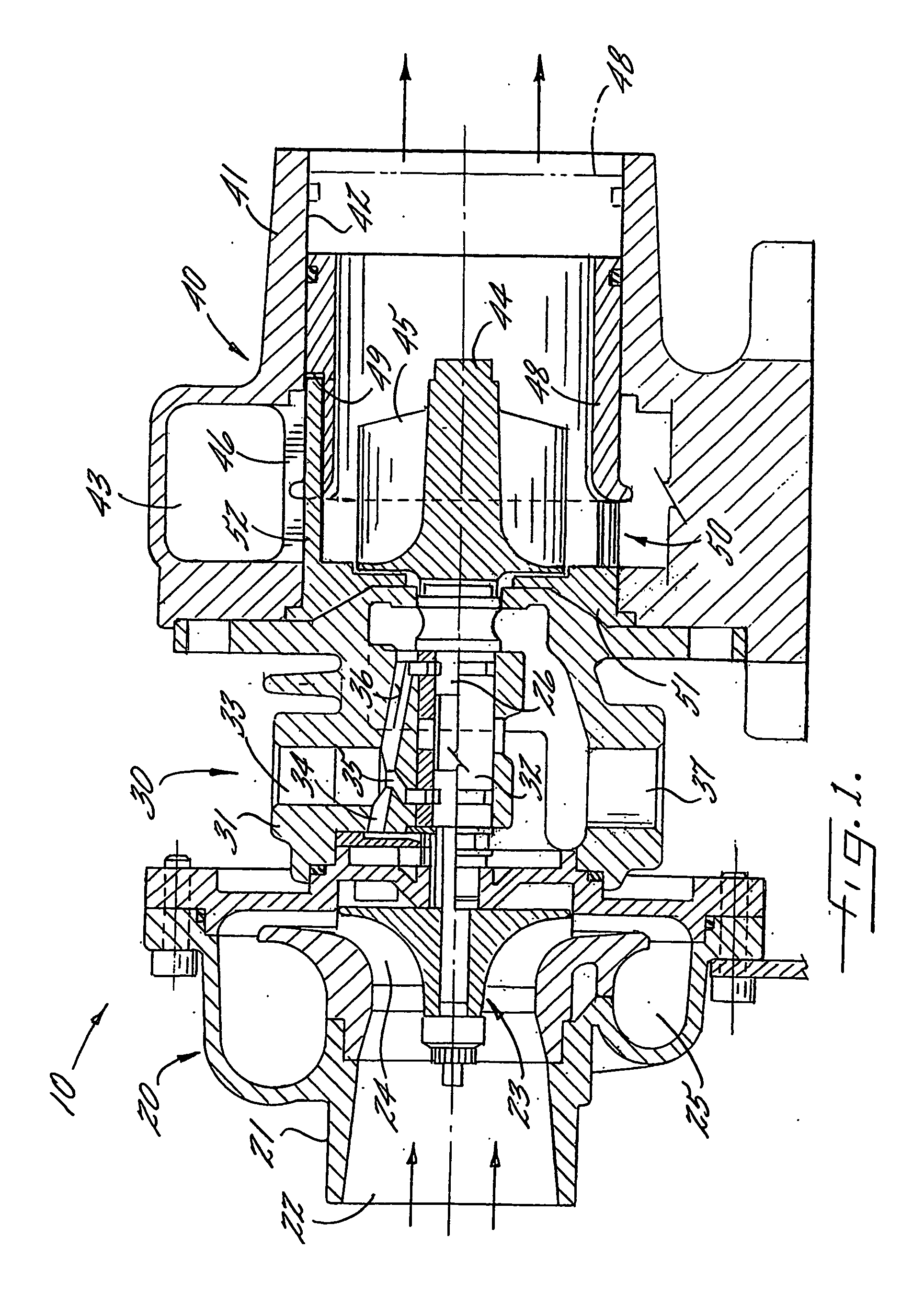
[0020]FIG. 1 illustrates a turbocharger 10 in accordance with one embodiment of the invention. The turbocharger 10 is similar in many respects to that described in U.S. Pat. No. 5,441,383, which is incorporated herein by reference. The major components or modules of the turbocharger include a compressor assembly 20, a center housing and bearing assembly 30, and a turbine assembly 40. The compressor assembly 20 comprises a compressor housing 21 that defines an axially extending air inlet 22 through which air to ...


PUM


Abstract

A turbine (40) for a turbocharger (10) has a turbine housing (41) defining a generally annular chamber (43) surrounding a turbine wheel (44), the chamber receiving exhaust gas for driving the turbine wheel. The chamber has dividing walls (46) that divide the chamber into a plurality of angular sectors (43a,43b), each fed with exhaust gas separately from the other sector(s). (52,53) located radially inwardly of the sectors for guiding flow into the turbine wheel include at least dividing vanes (52) that form extensions of the dividing walls (46) so as to extend the sector-division of the exhaust gas flow path all the way to the trailing edges of the dividing vanes. An axially slidable piston (48) is disposed radially inwardly of the sectors, and radially overlaps with the dividing vanes (52). The vanes either are mounted on fixed structure and are received in slots (49) in the piston, or are mounted on the piston and received in slots in fixed structure.

Description

BACKGROUND OF THE INVENTION[0001]1. Technical Field[0002]The invention relates to turbochargers in which a turbine of the turbocharger is driven by exhaust gas from a reciprocating engine. The invention relates more particularly to turbine housings that are divided into a plurality of substantially separate sections each fed by a separate exhaust system, and to turbochargers having a variable-geometry turbine for controlling the flow into the turbine.[0003]2. Description of Related Art[0004]In multiple-piston reciprocating engines, it is known to design the exhaust system in such a manner as to take advantage of the pressure pulsation that occurs in the exhaust stream. In particular, it is known to employ what is known as “pulse separation” wherein the cylinders of the engine are divided into a plurality of subgroups, and the pulses from each subgroup of cylinders are substantially isolated from those of the other subgroups by having independent exhaust passages for each subgroup. T...

Claims


Application Information

Patent Timeline
Patent Type & Authority Applications(United States)
IPC IPC(8): F01D9/02F01D17/14F01D17/16
CPCF01D9/026F05D2220/40F01D17/167F01D17/143
Inventor ROBERTS, QUENTINBERNARDINI, LUCIANOLOMBARD, ALAINPETITJEAN, DOMINIQUELOTTERMAN, JEFF
Owner HONEYWELL INT INC
Why Eureka
Try Eureka