Vehicular steering system

Inactive Publication Date: 2008-02-14
MITSUBISHI ELECTRIC CORP
View PDF7 Cites 28 Cited by
  • Summary
  • Abstract
  • Description
  • Claims
  • Application Information

AI Technical Summary

Benefits of technology

[0021]Accordingly, the present invention is intended to obviate the problems as referred to above, and has for its object to obtain a vehicular steering system which, even upon failure of a rotation angle sensor used for controlling the driving of

Problems solved by technology

However, when the pulse signals become unable to be obtained due to a break or disconnection of either of signal lines for the two-phase pulses, failure of the rotary encoder, etc., normal counting of the pulse signals becomes impossible in spite of an actual change in the steered angle θp, so the detected value of the steered angle θp or the auxiliary steering angle θs does not change.
Accordingly, the control of the auxiliary steering angle θs to be superposed by the auxiliary steering angle superposition mechanism becomes abnormal, and as a result, there is a possibility that the steerable road wheels might be steered in a direction not intended by the driver.
However, according to such a determination method, failure can not be detected until when the steering in the direct

Method used


Image

  • Vehicular steering system
  • Vehicular steering system
  • Vehicular steering system

Examples


embodiment 1

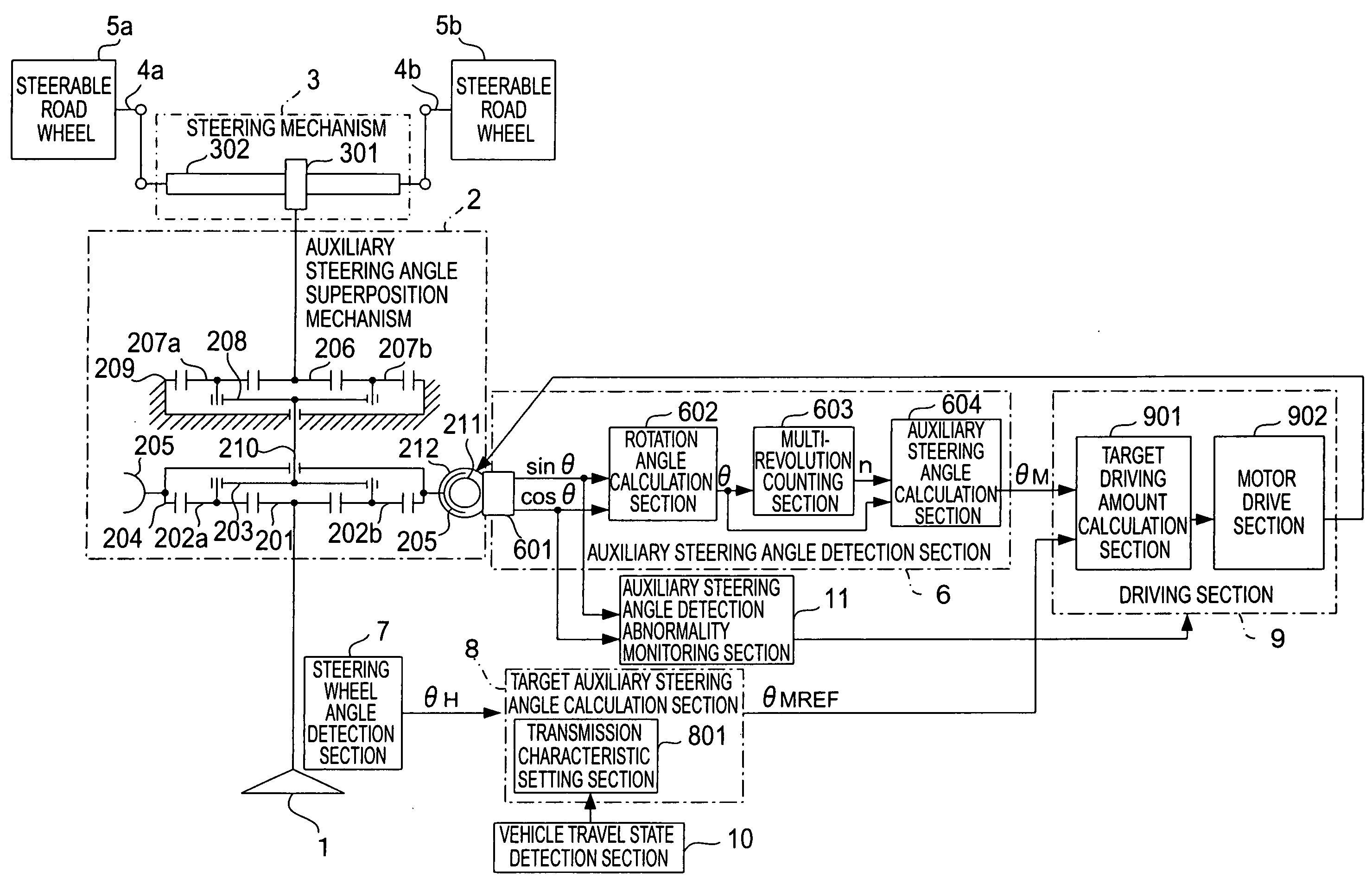
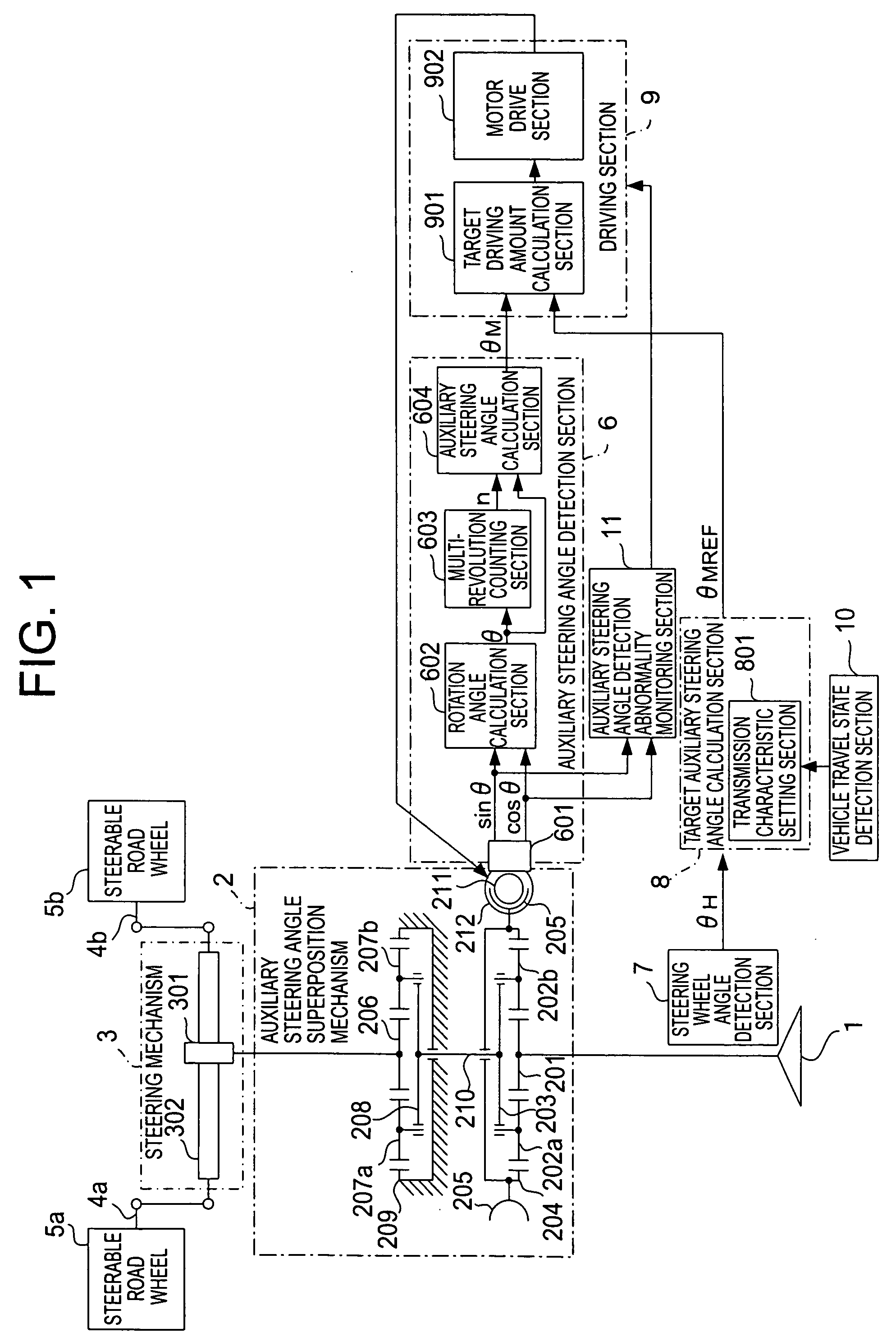
[0041]Referring to the drawings and first to FIG. 1, there is shown, in a block diagram, a vehicular steering system according to a first embodiment of the present invention. In FIG. 1, the vehicular steering system includes a steering wheel 1 that is steered by the driver of a vehicle, an auxiliary steering angle superposition mechanism 2 that is composed of two planetary gear mechanisms and an electrically controllable rotational member (to be described later), a steering mechanism 3 that steers steerable road wheels 5a, 5b of the vehicle according to the steering wheel 1 and the auxiliary steering angle superposition mechanism 2, and a pair of knuckle arms 4a, 4b that connect between the steering mechanism 3 and the steerable road wheels 5a, 5b, respectively.

[0042]In addition, the vehicular sterling system according to the first embodiment of the present invention further includes an auxiliary steering angle detection section 6 that detects an auxiliary steering angle θM to be su...

embodiment 2

[0096]In the above-mentioned first embodiment, the auxiliary steering angle detection abnormality monitoring section 11 stops the driving of the electric motor 212 by means of the driving section 9 when detecting the abnormal state of the auxiliary steering angle detection section 6, but upon detection of the abnormality of only one of the detection signals sin θ, cos θ, the rotation angle of the electric motor 212 may be estimated based only on the other normal detection signal, and the electric motor 212 may be driven by using the auxiliary steering angle θM calculated based on the thus estimated rotation angle.

[0097]FIG. 6 is a block diagram that shows a vehicular steering system with a rotation angle estimation section, which is activated upon detection of only one of the detection signals, according to a second embodiment of the present invention comprising the activated at the abnormality detection. In FIG. 6 the same parts or components as those described above (see FIG. 1) a...

embodiment 3

[0117]Although in the above-mentioned first and second embodiments, no mention has been made to the processing at the time when the control of the auxiliary steering angle superposition mechanism 2 is stopped and resumed through the auxiliary steering angle detection sections 6, 6A and the driving section 9, provision may be made for a nonvolatile storage section 14 that is connected to a microcontroller 130 including an auxiliary steering angle detection section 6, etc., as shown in FIG. 9, wherein the rotation angle θ (detected value) and the number of revolutions per minute n (count value) of a rotational member are stored in the nonvolatile storage section 14 when the control of an auxiliary steering angle superposition mechanism 2 is stopped, and the data thus stored are used for the control of the auxiliary steering angle superposition mechanism 2 when such control is restarted or resumed.

[0118]FIG. 9 is a block diagram that shows a vehicular steering system according to a thi...


PUM


Abstract

A vehicular steering system can suppress steering of steerable road wheels in a direction not intended by a driver. A steering mechanism steers the steerable road wheels in accordance with a steering wheel and an auxiliary steering angle superposition mechanism. A calculation section calculates a target auxiliary steering angle corresponding to a steering wheel angle of the steering wheel. A detection section accurately detects the auxiliary steering angle based on detection signals of a rotation angle sensor that detects a rotation angle of a rotational member. A driving section controls the auxiliary steering angle superposition mechanism so as to make the auxiliary steering angle coincide with the target auxiliary steering angle. An auxiliary steering angle detection abnormality monitoring section detects abnormality of the auxiliary steering angle detection section. The auxiliary steering angle detection section includes a counting section that counts the number of revolutions per minute of the rotational member.

Description

BACKGROUND OF THE INVENTION[0001]1. Field of the Invention[0002]The present invention relates to a vehicular steering system having a steering mechanism for steering the steerable road wheels of a vehicle in accordance with a value that is obtained by mechanically adding an auxiliary steering angle, which can be electrically controlled by an auxiliary steering angle superposition mechanism, to the steering wheel angle of a steering wheel steered by a driver. In particular, the invention relates to novel technical improvements for performing steering (intervention steering) to correct the steering operation of the steering wheel by the driver, and at the same time changing a transmission characteristic between the steering angle of the steering wheel operated by the driver and the steered angle of the steerable road wheels.[0003]2. Description of the Related Art[0004]Conventionally, there has been well known a vehicular steering system in which an auxiliary steering angle superpositi...

Claims


Application Information

Patent Timeline
IPC IPC(8): G05D3/14B62D5/04H02P7/00B62D6/10B62D6/00B62D113/00B62D137/00
CPCB60W50/0205B62D5/0487B62D5/0481B62D5/008
Inventor OGAWA, KENJIKIFUKU, TAKAYUKIYAMAMOTO, MASAYOSHIOKAZAKI, MASAFUMI
Owner MITSUBISHI ELECTRIC CORP
Why Eureka
Try Eureka