
Method for producing a pricking element

a technology of pricking element and method, which is applied in the direction of manufacturing tools, applications, diagnostic recording/measuring, etc., can solve the problems of not providing a particularly optimal puncture, reducing the problem of blunting, and not generally using mechanically stressed materials

Active Publication Date: 2008-02-21
ROCHE DIABETES CARE INC
View PDF9 Cites 111 Cited by
  • Summary
  • Abstract
  • Description
  • Claims
  • Application Information

AI Technical Summary

Benefits of technology

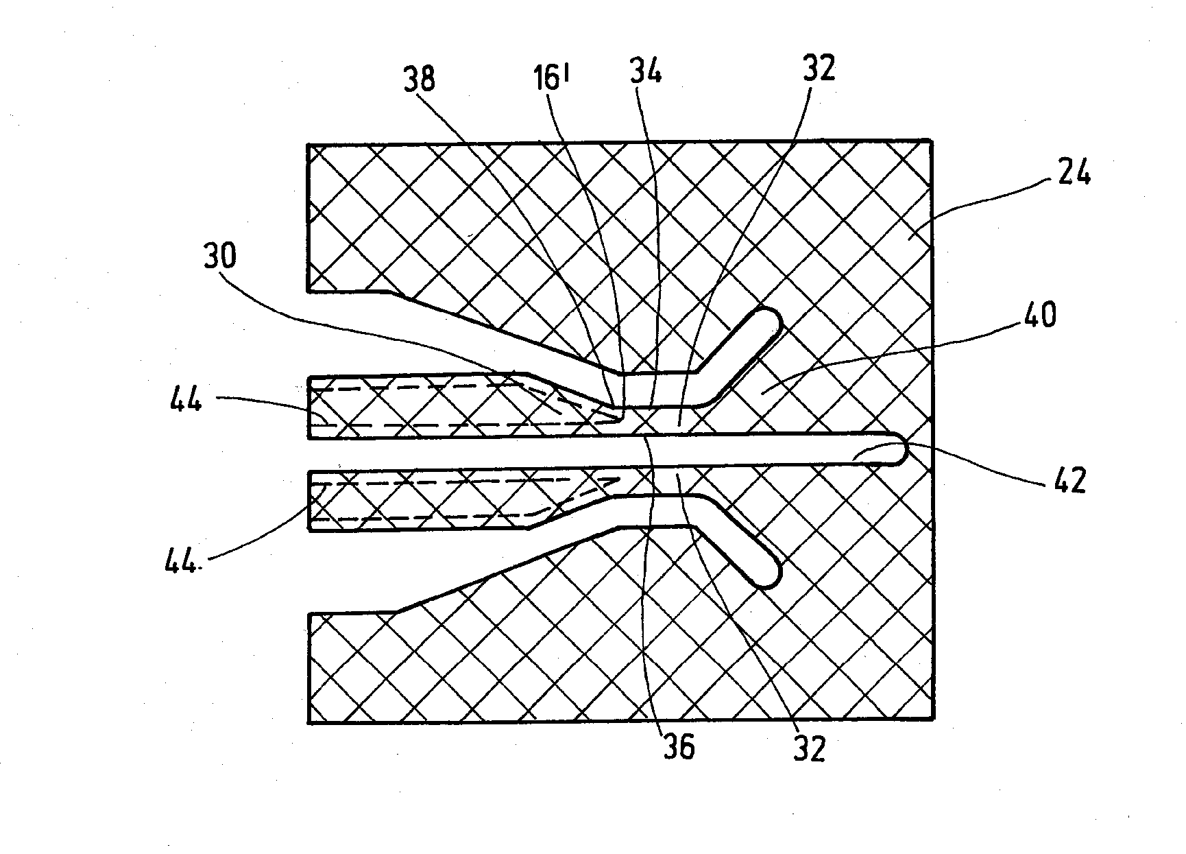
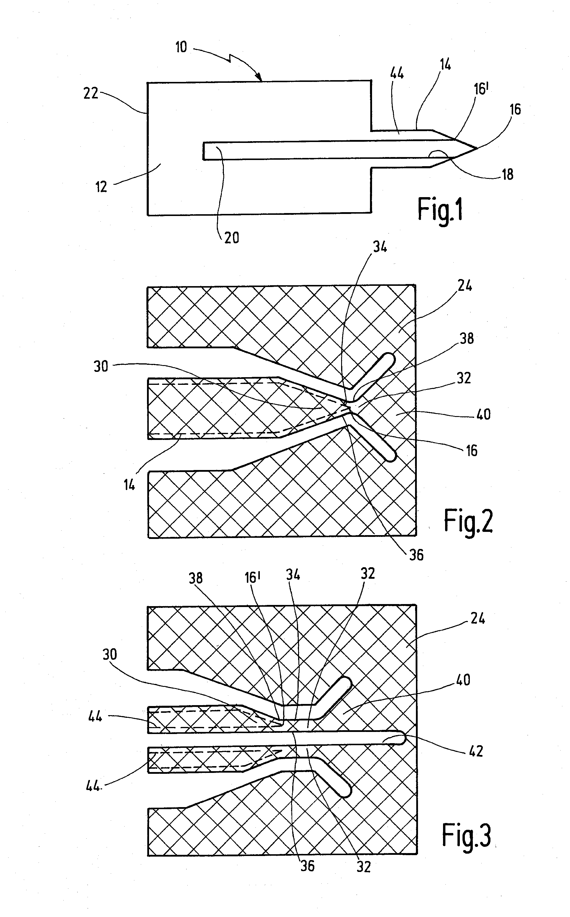
[0006] An exemplary embodiment produces a sharp tip solely by lateral and mutually converging etching agent fronts. In this embodiment, a mask is provided with a shaping area for the tip to be formed and a screening area which extends beyond this shaping area to prevent the tip from being etched off at the front. A sharp tip is exposed by laterally undercutting the side flanks or edges of the shaping and screening area. This can prevent the contour near the tip from being rounded off, whereby the etching process is terminated as soon as the bridge of material located between the side flanks of the etching mask is broken through. This allows optimized tips to be created in order to reduce the lancing pain and enable bodily fluid to be extracted with the smallest possible volume. Moreover, the required propulsion forces for lancing can be minimized and traumatization of the body tissue can be substantially reduced.
[0009] In an embodiment, the mask is constructed such that the screening area has a constant or increasing width over a given screening length where it connects with the shaping area. The screening length should be larger than the proximal undercutting width due to the action of the etching agent. This prevents the tip from being centrally etched off.
[0011] The screening area is advantageously widened again after the constriction. To improve the stability of the etching mask, it is advantageous when the screening area has a widening bridge section distal to the tip.
[0013] For high throughput, it is advantageous when the flat material that is formed from stainless steel sheet metal is processed from roll to roll by photo-chemical mask etching. However, it is also possible to use a semiconductor wafer as a flat material.
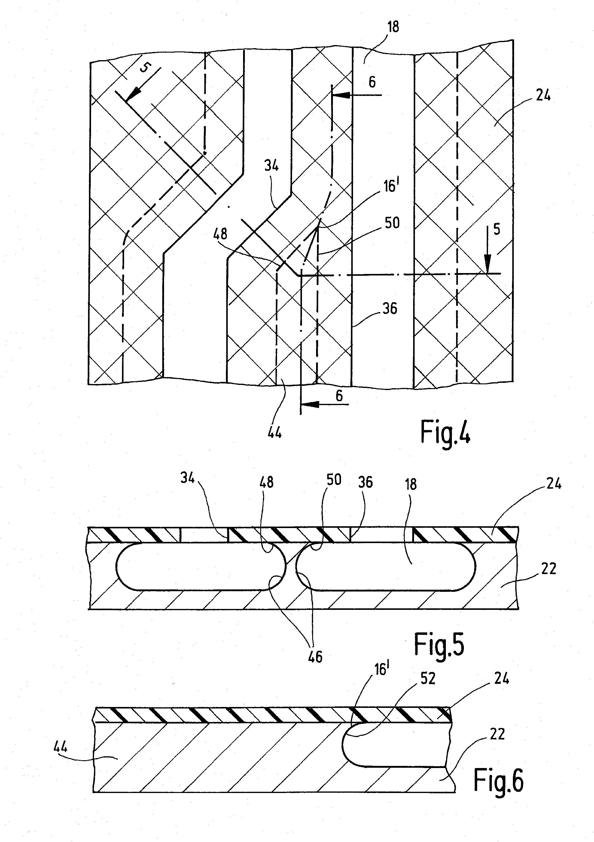
[0018] In order to remove the edges, it is advantageous when the compensation opening is a slot or chain of holes in the mask along the edge section. The compensation opening should have a smaller inner width than a cut-away or opening in the mask bordering the edge section.
[0021] In order to protect the tip from being etched away at the front, it is advantageous when the compensation opening is introduced at the side of a central axis running towards the tip that is to be formed so that a strip of the mask is retained in front of the tip along the central axis and at least beyond the undercutting width. In principle, the same considerations apply here with regard to avoiding a frontal action of the etching agent as already set forth with regard to the edge of the mask. In any case, a V-shaped contour of the compensation opening should be avoided.

Problems solved by technology

Although manufacturing processes, especially in the form of mask etching (photochemical etching), are known from the field of semiconductor technology for highly-integrated systems, the materials used cannot generally be used for mechanically stressed structures due to their brittleness.
When biocompatible materials such as steel are etched, a problem arises with conventionally shaped-complementary etch masking in which the generated lancing structures are rounded off at the tip and thus do not provide a particularly optimal puncture.
However, this mask overhang is shorter than the undercutting width of the etching agent so that the tip is shaped by a combined lateral and frontal etching action which only slightly reduces the problem of blunting.

Method used


Image

  • Method for producing a pricking element
  • Method for producing a pricking element
  • Method for producing a pricking element

Examples


Embodiment Construction

[0033] The embodiments of the present invention described below are not intended to be exhaustive or to limit the invention to the precise forms disclosed in the following detailed description. Rather, the embodiments are chosen and described so that others skilled in the art may appreciate and understand the principles and practices of the present invention.

[0034] The lancing and sampling element 10 shown in FIG. 1 is used as a disposable article to withdraw and transport a small amount of blood through capillary action from a body part of a test subject to an analytical site 20, for example, to carry out blood glucose measurements. In this exemplary embodiment, the lancing element 10 comprises a flat-shaped member 12, a lancing member 14 extending therefrom and having a tip 16, and a semi-open capillary channel 18 for blood transport through capillary action from the tip 16 to the analytical site 20.

[0035] The flat-shaped member 12 is made of a stainless steel metal sheet 22 hav...


PUM

PropertyMeasurementUnit
Thicknessaaaaaaaaaa
Thicknessaaaaaaaaaa
Lengthaaaaaaaaaa

Abstract

The present invention provides a process for producing a lancing element in which a flat-shaped member is formed from a flat material by applying a mask and allowing an etching agent to act upon it, wherein at least a part of the flat-shaped member is shaped as a tip. The mask is provided with a shaping area for the tip to be formed and with a screening area which extends distally beyond this shaping area to prevent the tip from being etched off at the front. A sharp tip is exposed by laterally undercutting the side flanks of the shaping area and screening area.

Description

RELATED APPLICATIONS [0001] This is a continuation application of International Application PCT / EP2005 / 013266, filed Dec. 10, 2005, which claims priority to EP 04029926.5, filed Dec. 17, 2004, which are hereby incorporated by reference in their entirety.BACKGROUND [0002] The present invention relates to a process for producing a lancing element for withdrawing bodily fluid in which a flat-shaped member is formed from a flat material by applying a mask and allowing an etching agent to act upon it. At least a part of the flat-shaped member is shaped as a tip for piercing into a body part of a test subject. [0003] Lancing elements of this type are used for the analysis of very small amounts of fluid, especially in bioanalytics, such as those which are withdrawn in situ as capillary blood for blood glucose determinations. Such microfluidic systems, in addition to the microscopic volumes (microliters and less), are also characterized by structural elements of increasingly smaller dimensi...

Claims


Application Information

Patent Timeline
IPC IPC(8): A61B17/34
CPCA61B5/1411A61M37/00Y10T29/302Y10T29/49995Y10T29/53339Y10T29/49812Y10T428/12188Y10T29/304A61B5/150022A61B5/150282A61B5/150419A61B5/15105A61B5/15142A61B5/1405
Inventor GRISS, PATRICKZIPFEL, MARZELLINUSLOPEZ, ANGEL
Owner ROCHE DIABETES CARE INC
Learn More