Photoelectric conversion device

a conversion device and photoelectric technology, applied in the direction of electrolytic capacitors, pv power plants, capacitors, etc., can solve the problems of limited metal usable device substrates, complicated fabrication process of devices, and high cost of devices such as conductive glass, so as to achieve high device photoelectric conversion efficiency and high performance. stability

Inactive Publication Date: 2008-02-21
DAI ICHI KOGYO SEIYAKU CO LTD
View PDF4 Cites 34 Cited by
  • Summary
  • Abstract
  • Description
  • Claims
  • Application Information

AI Technical Summary

Benefits of technology

The technical effect of this patent is the discovery of a specific chemical combination (represented by a certain formula) which works well at converting light into electricity in photovoltaic devices. When combined with a special type of material called a conductive polymer catalyst, it forms highly efficient solar cells. This solution offers improved performance and stability compared to other similar combinations.

Problems solved by technology

The technical problem addressed in this patent text is finding an alternative to the commonly used iodine-based oxidation-reduction pair in photovoltaic converters due to issues related to cost, limitations in material selection, and potential environmental concerns associated with iodine's volatility and corrosiveness. Other alternatives include cobalt and selenium based systems, but each has its own set of challenges including slow movement speeds and poor performance under sunlight conditions. Therefore, there is a desire for a new oxidation-reduction pair that overcomes these shortcomings and provides improved practicality and efficiency of photosynthetic conversion devices.

Method used


Image

  • Photoelectric conversion device
  • Photoelectric conversion device
  • Photoelectric conversion device

Examples


example 1

Formation of Porous Metal Oxide Semiconductor

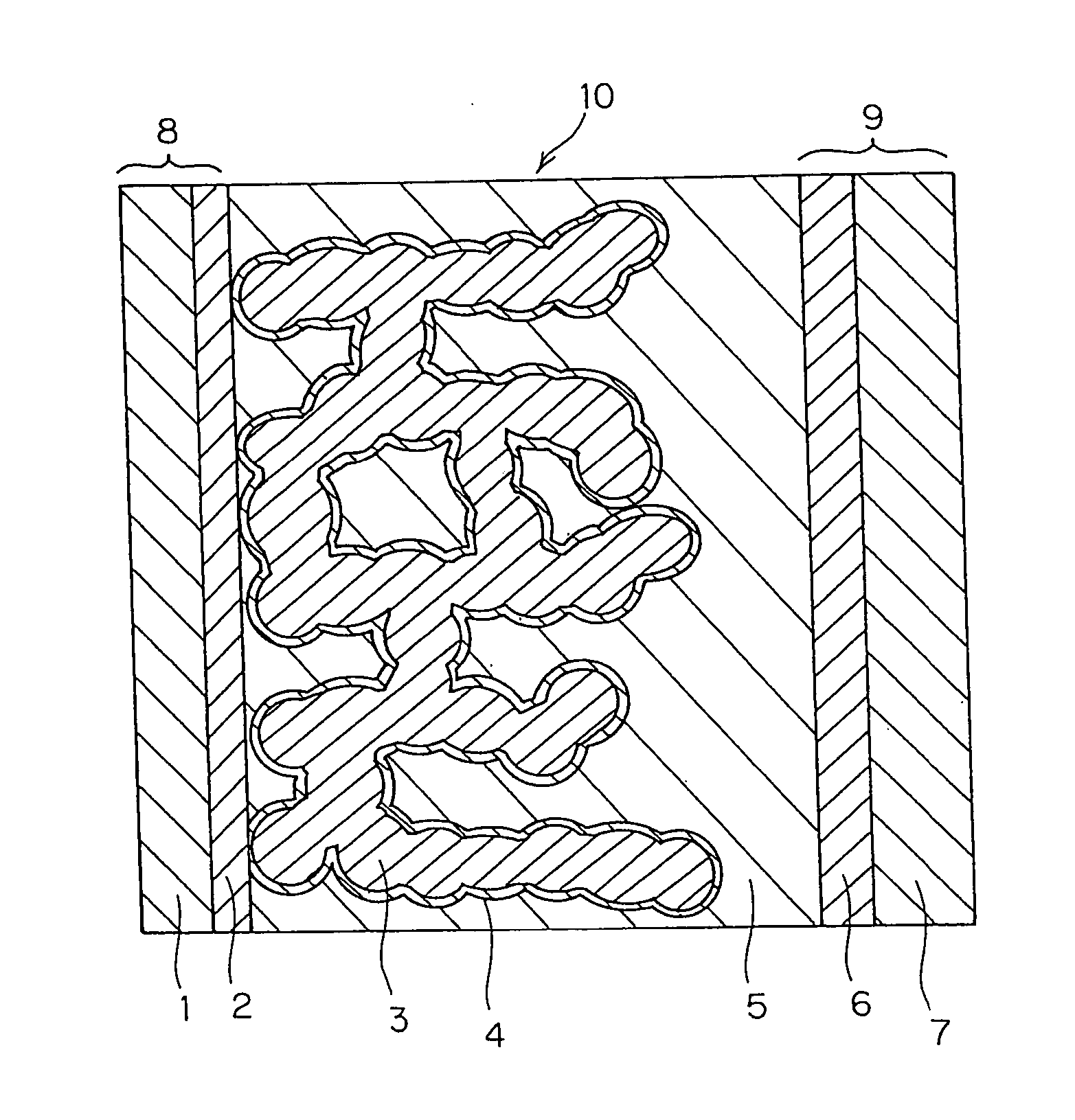
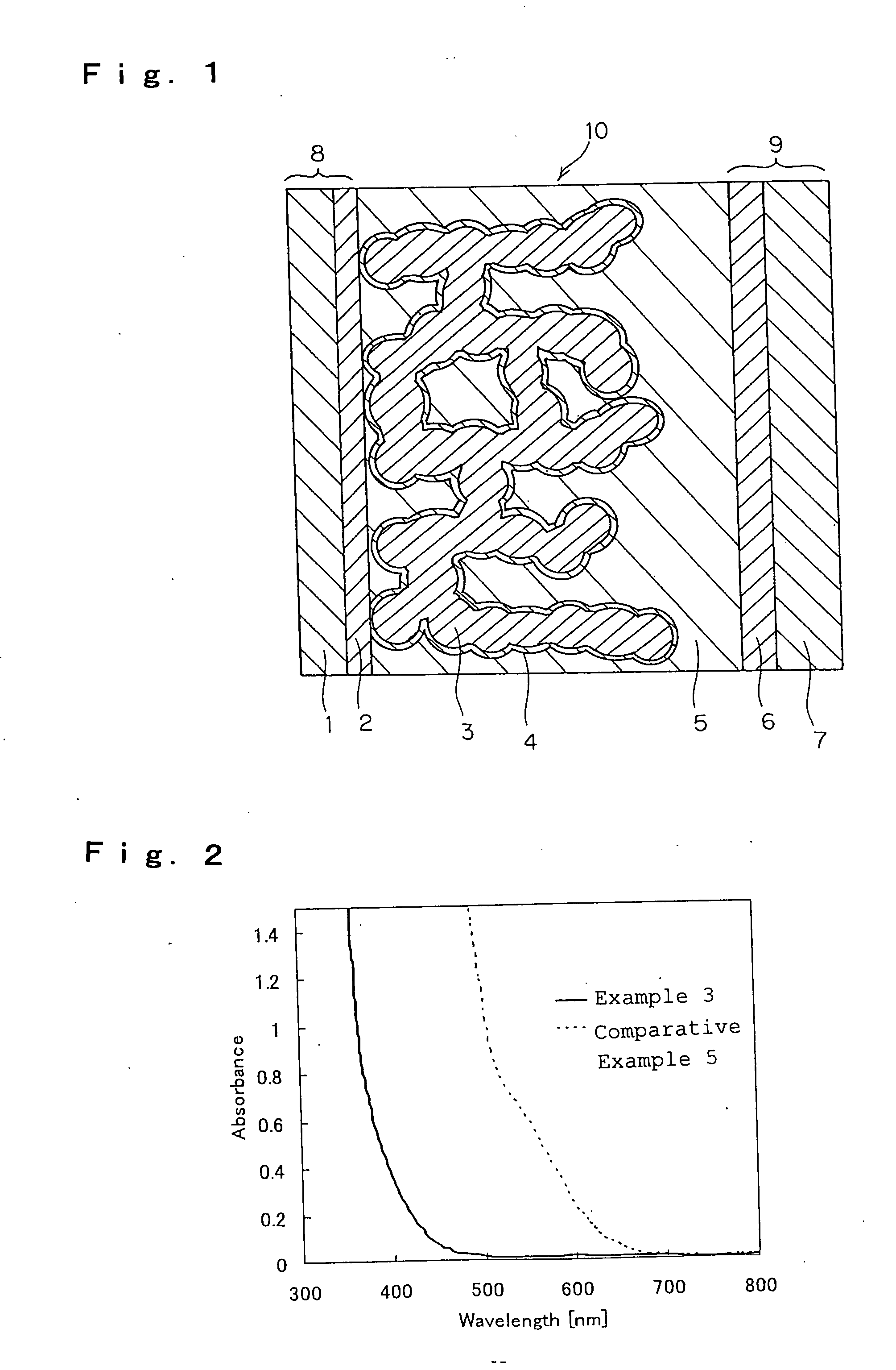
[0101] A transparent conductive film of fluorine-doped SnO2 was formed on a transparent substrate 1 of glass, through vacuum evaporation to from a transparent conductive film 2, on which was formed a porous metal oxide semiconductor layer 3 according to the following method:

[0102] As the electrode substrate 8 with the transparent conductive film 2 formed on the transparent substrate 1, used was FTO glass (by Nippon Sheet Glass). To its surface, applied was a commercially-available titanium oxide paste (by Shokubai Kasei, trade name TSP-18NR, having a particle size of 20 nm) according to a screen-printing method to form a film having a thickness of 6 μm or so and an area size of 5 mm×10 mm or so, on the side of the transparent conductive film 2; and further on it, a commercially-available titanium oxide paste (by Shokubai Kasei, trade name TSP-400C, having a particle size of 400 nm) was applied according to a screen-printing method to th...

example 2

[0107] A solar cell was produced in the same manner as in Example 1, for which, however, 1-methyl-3-ethylimidazolium bis(trifluoromethanesulfonyl)imide was used as the solvent for the electrolyte layer 5.


PUM


Abstract

Provided is an inexpensive and high-performance photoelectric conversion device of high practicability. The device comprises a semiconductor electrode, a counter electrode and an electrolyte layer held between the two electrodes, in which the electrolyte layer contains a compound of the following general formula (1) as an oxidation-reduction pair therein:
(wherein M+represents an organic or inorganic cation; A represents an aromatic, non-aromatic, heteroaromatic or hetero-non-aromatic cyclic compound).

Description


Claims


Application Information

Patent Timeline
Owner DAI ICHI KOGYO SEIYAKU CO LTD
Why Eureka
Try Eureka