Solar concentrator device for photovoltaic energy generation

a technology of photovoltaic energy and solar concentrator, which is applied in the direction of photovoltaics, solar heat devices, solar-ray concentration, etc., can solve the problems of loss of conversion efficiency, poor boundary sharpness, and further loss of efficiency, and achieve accurate and uniform solar illumination.

Inactive Publication Date: 2008-02-21
SCHWARTZMAN ZALMAN
View PDF7 Cites 72 Cited by
  • Summary
  • Abstract
  • Description
  • Claims
  • Application Information

AI Technical Summary

Benefits of technology

[0015]It is an object of the present invention is to provide an optical concentrator for photovoltaic solar energ...

Problems solved by technology

There are several problems with this approach.
First, when a rectangular lens is cut from circular grooved Fresnel lens in an attempt to match the target, the intensity of the sun projected on the target area is non uniform, leading to loss of conversion efficiency.
The second problem is that the sharpness of the boundaries is usually poor; a significant area out of the cell is illuminated leading to further loss of effic...

Method used


Image

  • Solar concentrator device for photovoltaic energy generation
  • Solar concentrator device for photovoltaic energy generation
  • Solar concentrator device for photovoltaic energy generation

Examples


Embodiment Construction

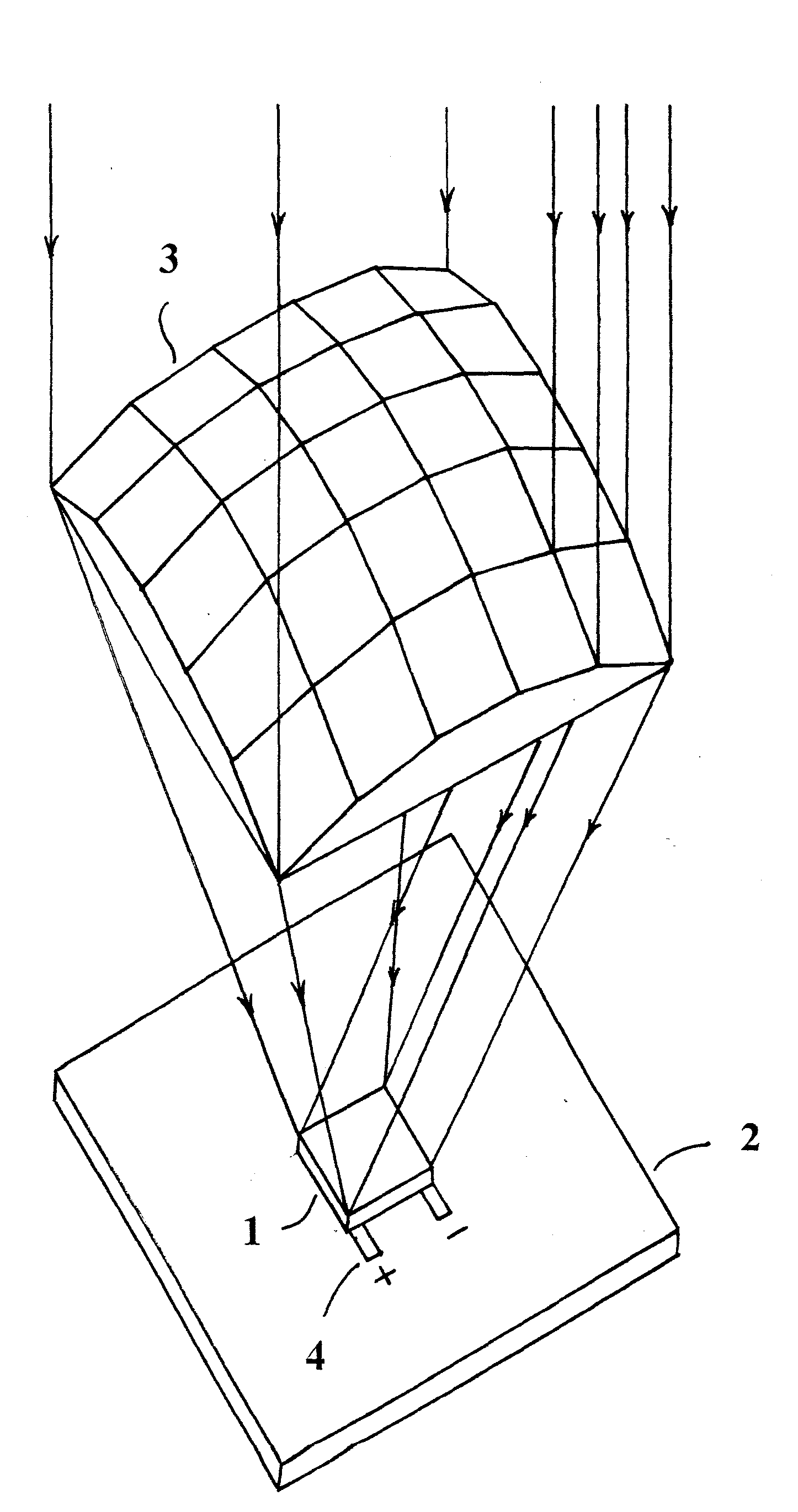
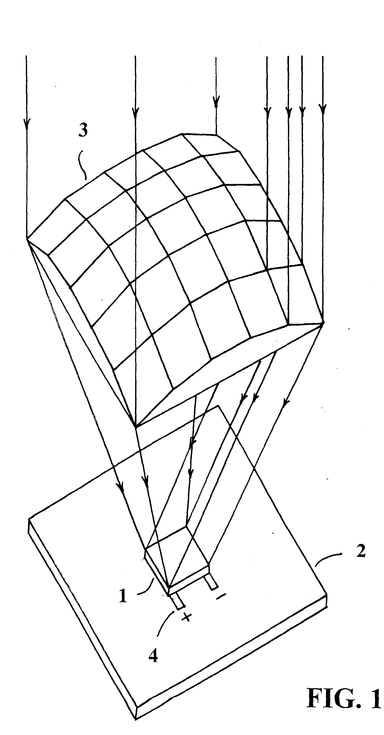
[0058]As illustrated in FIG. 1, a square photovoltaic cell 1 is mounted on a heat sink plate 2. A 25 facet concentrating lens 3 in accordance with the present invention is located above the photovoltaic cell; the cell is within a concentrated illumination target area of the lens, converting the solar energy to electrical energy being transferred to the load through terminals 4.

[0059]25 facets were chosen for convenience of drawing. However, all the descriptions apply to any number of facets and shapes, as required for a specific concentration ratio and specific photovoltaic cell, by appropriately modifying the lens design.

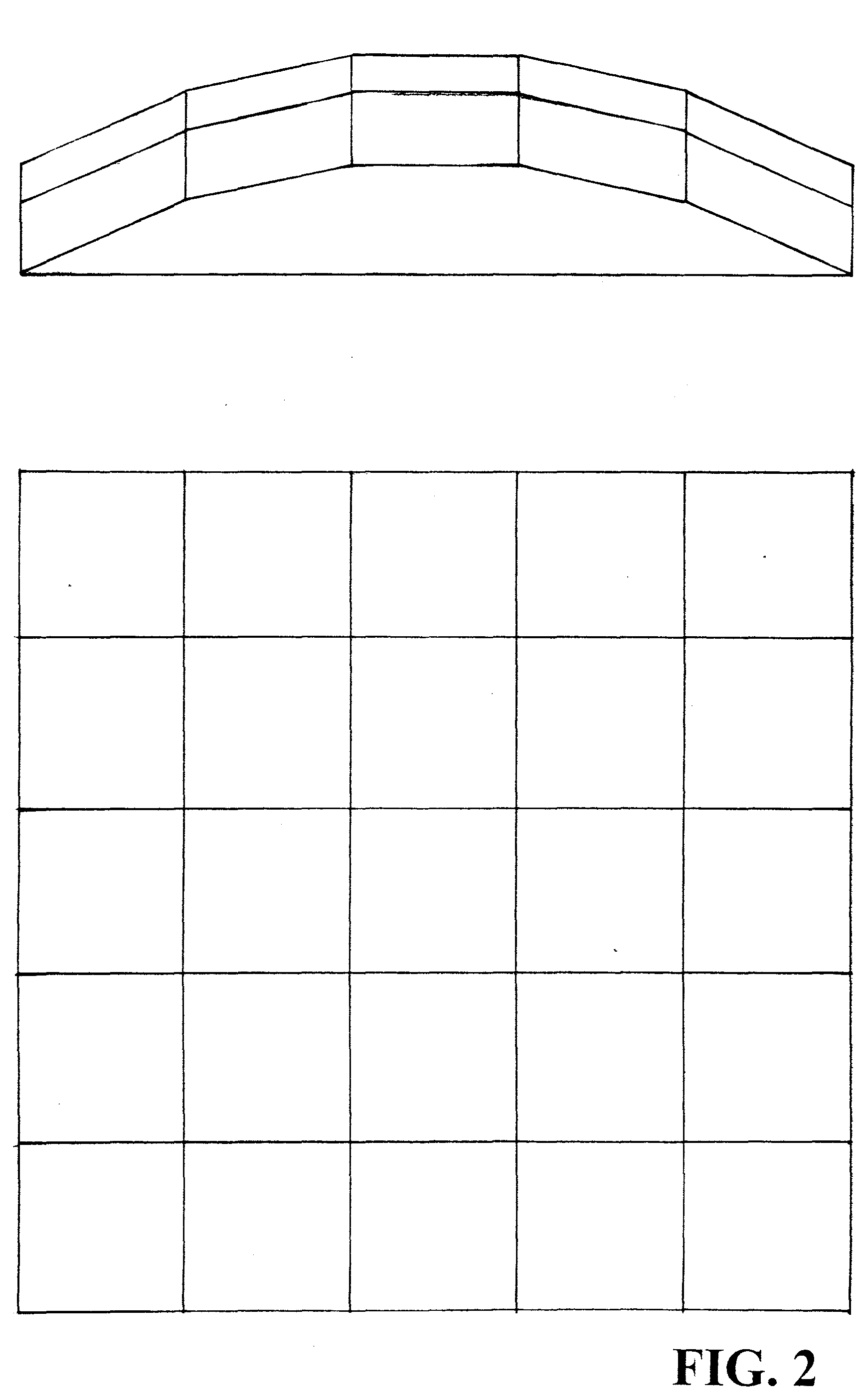
[0060]FIG. 2 is a top view and side view of the lens of FIG. 1 showing each facet as a square when viewed from the top.

[0061]FIG. 3 is a cross section view of the lens of FIG. 2, showing the solar rays 5 refracted by each planar facet of the lens, fully illuminating the rectangular target 6 with well defined uniform light intensity.

[0062]The basic aspect of the inv...


PUM


Abstract

A solar energy concentrator lens is formed by a prism array. Each prism is designed to deflect the incident solar rays and fully illuminate a rectangular photovoltaic cell with uniform intensity. The combination of multiple prisms uniformly illuminating a common target area yields concentrated uniform illumination across the target area.

Description

FIELD OF THE INVENTION[0001]This invention relates to a new optical concentrator, designed for concentrated photovoltaic solar energy generation.BACKGROUND OF THE INVENTION[0002]Solar energy conversion modules that convert sunlight to electrical power typically employ photovoltaic cells that directly convert sunlight to electrical energy.[0003]Concentrating methods for increasing the light intensity on the cell are usually employed. Such methods include using concentrator lenses and / or reflectors to focus the sun on the cell. See, e.g., U.S. Pat. No. 6,020,554 which utilizes a Fresnel lens in combination with rectangular reflectors closely mounted to the photovoltaic cell.[0004]Two axis sun tracking servomechanism have been developed to keep the lens axis directed to the sun at all times during the day (e.g., U.S. Pat. Nos. 4,628,142 and 4,498,456).[0005]The photovoltaic cell is considered to be the most expensive component in a solar energy converter, therefore increasing the solar...

Claims


Application Information

Patent Timeline
IPC IPC(8): H01L31/052
CPCF24J2/062F24J2/085G02B5/001H01L31/0547H01L31/052Y02E10/52H01L31/0543G02B5/045F24S23/31F24S23/10
Inventor SCHWARTZMAN, ZALMAN
Owner SCHWARTZMAN ZALMAN
Why Eureka
Try Eureka