Modular Reusable Vehicle Shipping Crate

a reusable vehicle and module technology, applied in the field of modules, can solve the problems of inordinate space occupation of disassembled dunn crate, inconvenient disassembly and assembly of the crate, and large complexity and sturdiness of the respective crate housing the article, so as to avoid excessive deflection of the frame components, avoid deflection of the crate, and minimize the amount of space occupied

Inactive Publication Date: 2008-02-21
GATEWOOD PRODS
View PDF31 Cites 8 Cited by
  • Summary
  • Abstract
  • Description
  • Claims
  • Application Information

AI Technical Summary

Benefits of technology

[0013] It is an aspect of the present invention to provide a shipping crate with top and bottom portions thereof that can be compacted with one another when the crate is empty to minimize the amount of space occupied by the empty, disassembled, crate.
[0014] It is a further aspect of the present invention to provide a shipping crate that provides a sturdy container in which to transport large, heavy, objects.
[0015] It is a further aspect of the present invention to provide a shipping crate with a sturdy frame and which avoids excessive deflection of the frame components and provides continuous rigidity throughout the frame at all times, e.g., when an article is stored within and when disassembled and compacted for return to the shipper or other location when empty.
[0016] Further, aspects of a shipping crate consistent with the present invention include easy compaction to a much smaller size after the contents have been removed so as to enable efficient, space-saving, return of the empty containers; sturdy construction to avoid deflection of the crate during transport and to avoid “hopping”.
[0017] A crate in accordance with the present invention comprises a top portion including a plurality of top cross-members each fixedly attached to one or more top corner portions and a bottom portion comprising a plurality of bottom cross-members each fixedly attached to one or more bottom corner portions. To provide a sturdy configuration and to permit efficient compaction of the crate when empty, the top corner portions and the bottom corner portions are operable to telescopically engage each other. Each of the top, bottom and corner portions can be made of tubular metal components or other suitable material that provides a sturdy frame and telescoping engagement of the components.
[0018] Also, in accordance with the present invention, to accommodate the telescoping engagement of the corner components, the outer dimension of each of either the top or bottom corner portions is smaller than the inner dimension of the other of the top or bottom corner portions. Leg portions, each comprising two ends and each end being operable to engage a respective top or bottom corner portion can also be used to construct a shipping crate in accordance with the present invention. The inner dimension of one of the ends of the legs is such that it can telescopically fit into either a top or bottom corner portion and the outer dimension of the other end of the legs is such that it can telescopically be received into an opposing top or bottom corner portion.

Problems solved by technology

When the weight and / or value of the article being shipped within a particular crate are relatively large, the complexity and sturdiness of the respective crate housing the article is also relatively large.
However, the previously proposed crates suffer from various disadvantages as discussed below.
In particular, although the Dunn shipping crate can likely be disassembled after it is used for shipping an ATV, and can be returned to the shipper to be reused, the disassembled Dunn crate takes up an inordinate amount of space, thereby, wasting valuable cargo space when shipping the disassembled crate back to the shipper for reuse.
Further, crates like the one disclosed in Dunn are susceptible to “racking” when weight is placed on top of the crate.
Oftentimes, when a structure, such as the rectangular Dunn crate, is moved rapidly, such as by being transported in a truck, the top of the structure will move out of alignment with the bottom of the structure and place undue strain on the joints of the structure.
If the Beck crate were disassembled after use, for example to return the empty crate to the shipper for reuse, the Beck crate would take up an excessive amount of valuable space on the vehicle of the return-shipper.
Also, like the Dunn crate above, the Beck crate is susceptible to racking.
Thus, when used to carry stacked heavy loads, the joints, particularly in the corners of the crate, are vulnerable to cracking, or other forms of deterioration.

Method used


Image

  • Modular Reusable Vehicle Shipping Crate
  • Modular Reusable Vehicle Shipping Crate
  • Modular Reusable Vehicle Shipping Crate

Examples


Embodiment Construction

[0050] Exemplary, non-limiting, embodiments of the present invention are discussed in detail below. While specific configurations and dimensions are discussed to provide a clear understanding, it should be understood any disclosed dimensions and configurations are provided for illustration purposes only. A person skilled in the relevant art will recognize that other dimensions and configurations may be used without departing from the spirit and scope of the invention.

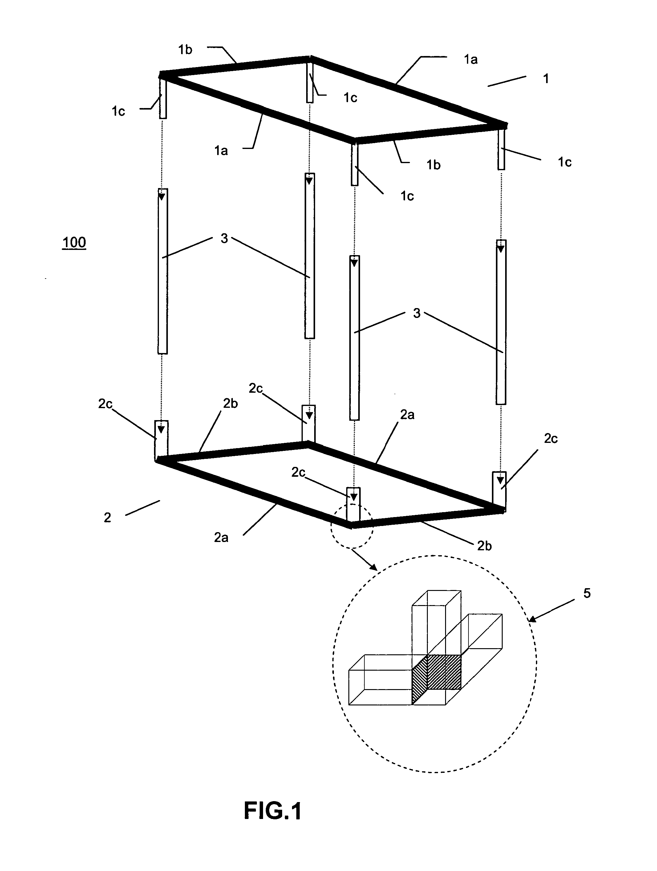
[0051]FIG. 1 illustrates an exploded view of a shipping crate in accordance with one exemplary embodiment of the present invention. As shown in FIG. 1, a crate 100 according to the present invention comprises a rectangular top frame 1, a corresponding rectangular bottom frame 2 and legs 3. Rectangular top frame 1 comprises two parallel top length bars 1a and two parallel top cross bars 1b which are perpendicular to length bars 1a. Attached at each corner of top frame 1 is a top corner portion 1c which is fixedly attach...


PUM


Abstract

A shipping crate for shipping objects such as all-terrain vehicles and personal water-crafts. The shipping crate includes a top frame structure and a bottom frame structure. The crate may include an extension removably connectable to the bottom frame structure. The crate may include at least one pivotally mounted leg.

Description

I. CROSS REFERENCE TO RELATED APPLICATIONS [0001] This continuation-in-part application claims benefit under 35 U.S.C. §120 of patent application Ser. No. 11 / 172,860 filed on Jul. 5, 2005 and benefit under 35 U.S.C. §119 to Provisional Application 60 / 588,046 filed on Jul. 15, 2004, the entire contents of both applications are incorporated by reference herein.II. FIELD OF THE INVENTION [0002] The present invention is directed to a shipping crate. More particularly, the present invention is directed to a shipping crate for transporting objects such as, for example, an all-terrain vehicle (ATV) or personal water craft (PWC). The shipping crate is constructed with a sturdy frame such that the contents of the container are protected from external damage while the crate and its contents are being shipped from one location to another, for example, via a tractor trailer, a railcar or a boat. III. BACKGROUND OF THE INVENTION [0003] Often, upon reaching their appointed destination and being u...

Claims


Application Information

Patent Timeline
Patent Type & Authority Applications(United States)
IPC IPC(8): B65D85/68B65D85/62
CPCB65D19/18B65D2585/686B65D2519/00024B65D2519/00059B65D2519/00164B65D2519/00199B65D2519/00233B65D2519/00268B65D2519/00293B65D2519/00532B65D2519/00557B65D2519/00686B65D2519/00711B65D2519/00815B65D2519/0082B65D2519/0096B65D2519/0097B65D85/68Y02W30/80
Inventor ARNOLD, W. CRAIG
Owner GATEWOOD PRODS
Why Eureka
Try Eureka