Electronic Ballast With Preheating and Dimming Control

a technology of electronic ballast and control, which is applied in the direction of electric variable regulation, process and machine control, instruments, etc., can solve the problems of unstable operation, no control for preheating, and gas discharge light sources that cannot be started

Inactive Publication Date: 2008-02-21
CENTURY CONCEPT
View PDF26 Cites 27 Cited by
  • Summary
  • Abstract
  • Description
  • Claims
  • Application Information

AI Technical Summary

Benefits of technology

[0013] This application discloses a ballast circuit for controlling preheating, ignition or performing dimming of a gas discharge lamp such as a compact fluorescent lamp. The inventive ballast circuit provides a built-in dynamic and/or adjustable frequency control to perform various functions such as preheating, ignition and dimming. In contrast to conventional electro

Problems solved by technology

For this reason, gas discharge lamps, particularly fluorescent lamps, provide a large percentage of today's lighting needs, even though they are more complicated to manufacture and require electronics to provide the correct current flow through the gas.
Unlike incandescent light sources, gas discharge light sources will not be able to start if directly connected to a regular voltage resource.
The negative resistance characteristics may result in an unstable operation if the lamp is directly connected to the voltage source.
A quasi-instant start circuit is similar in operation to the instant start circuit except that the quasi-instant start circuit allows the resonant current of the ballast to run through the lamp filaments (typically for disabling high-voltage generation by the resonant circuit during lamp removal), but like the instant-start circuit, does not have a preheating stage and therefore has no control for performing preheating.
Attributes such as cost, lamp life, ballast size, application and the nu

Method used


Image

  • Electronic Ballast With Preheating and Dimming Control
  • Electronic Ballast With Preheating and Dimming Control
  • Electronic Ballast With Preheating and Dimming Control

Examples


Embodiment Construction

[0033] The ballast circuit in accordance with the present invention for controlling preheating, ignition or performing dimming of a gas discharge lamp such as a compact fluorescent lamp will be described in detail along with the figures, in which like parts are denoted with like reference numerals or letters.

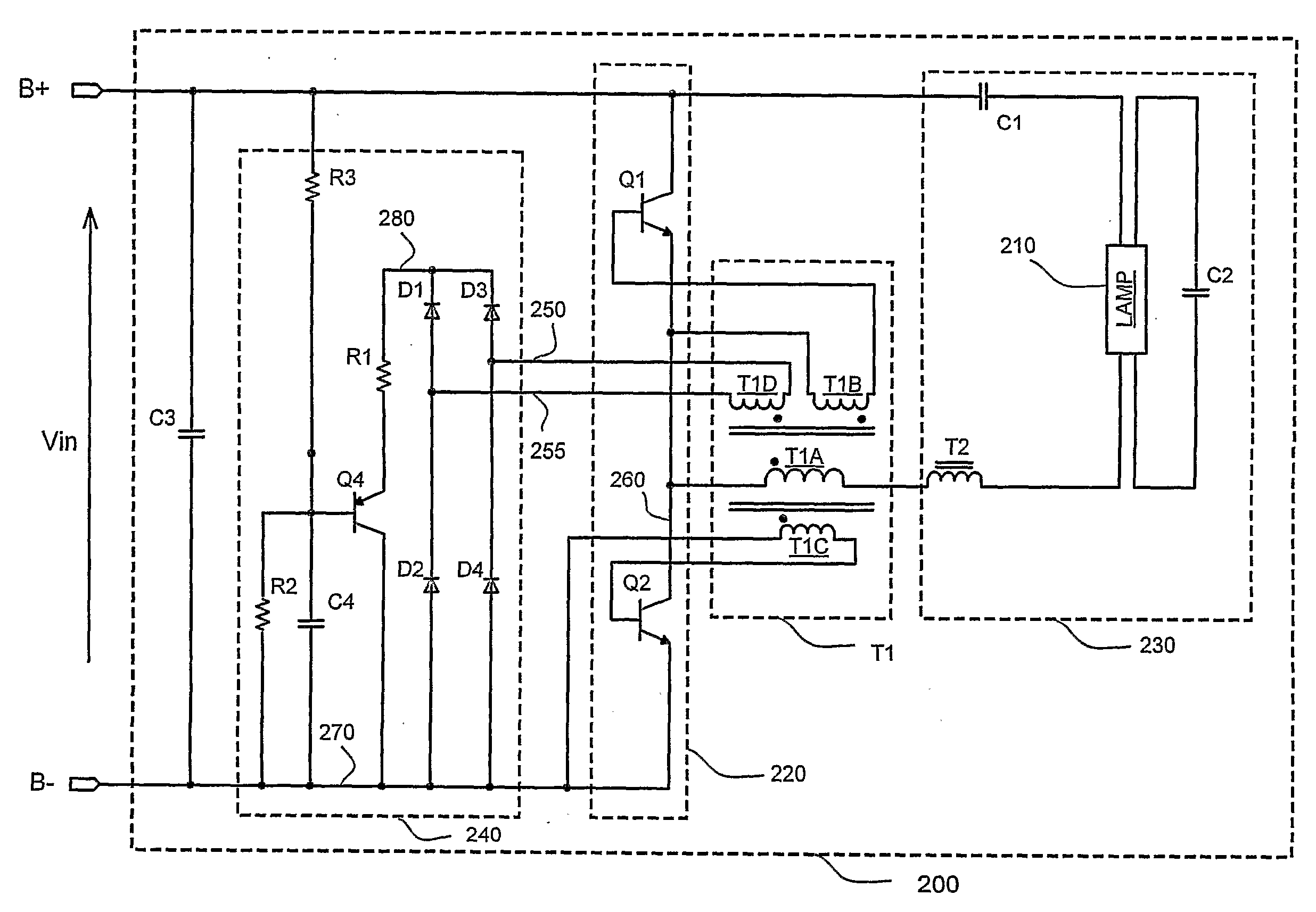
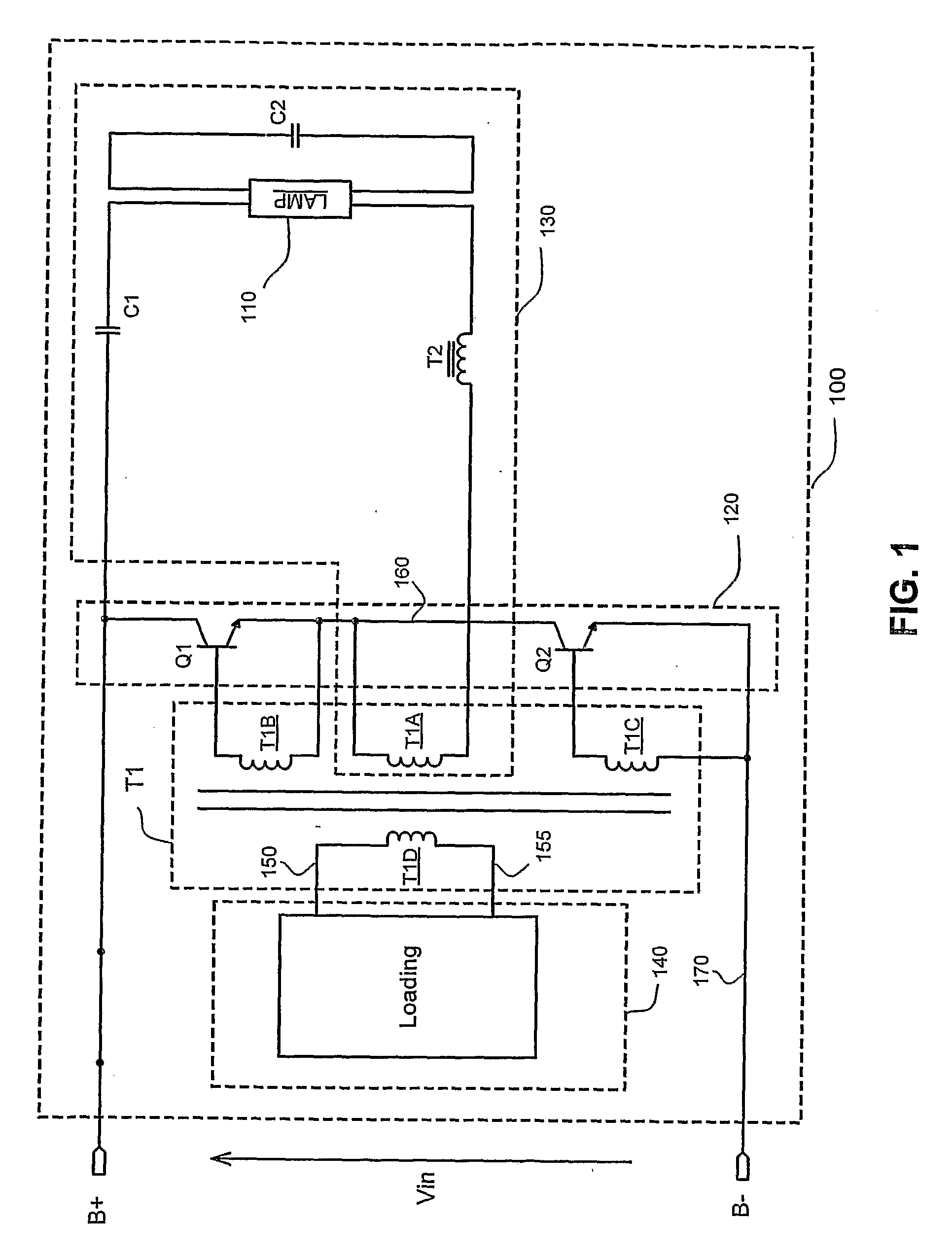
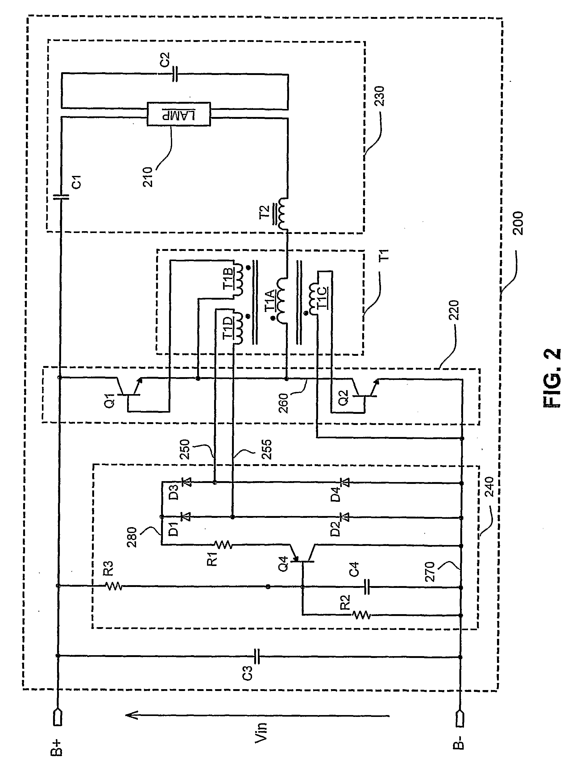
[0034]FIG. 1 shows an equivalent circuit model of an embodiment of a ballast that employs preheating and / or dimming control in accordance with the present invention. The ballast includes a ballast circuit 100 for powering a gas discharge lamp 110. The ballast circuit 100 has positive and negative DC input terminals B+ and B− for receiving a DC supply voltage. Additionally, the ballast circuit 100 includes, as represented by the circuit blocks of FIG. 1, an inverter 120, a base drive transformer T1, a resonant circuit 130 and a drive transformer loading circuit 140.

[0035] The inverter 120 is connected to the input terminals B+ and B−. The base drive transformer T1 is connected ...


PUM


Abstract

A ballast circuit for controlling preheating, ignition or performing dimming of a gas discharge lamp such as a compact fluorescent lamp is disclosed. The ballast circuit has an inverter connected to a pair of input terminals for receiving a supply voltage, a base drive transformer connected to the switching transistor inverter to provide a drive signal, a resonant circuit connected to the switching transistor inverter, and a loading circuit connected to the base drive transformer. The base drive transformer includes a primary winding and a secondary winding set. The loading circuit is adapted for at least temporarily saturating the base drive transformer and thus effecting in the resonant circuit an oscillating frequency different from a natural resonant frequency of the resonant circuit.

Description

PRIORITY [0001] This application claims the benefit of U.S. Provisional Application No. 60 / 631,192, filed Nov. 29, 2004, which is incorporated by reference herein in its entirety.FIELD OF THE INVENTION [0002] The present invention relates to ballasts of gas discharge lamps such as fluorescent lamps, and more particularly to electronic ballast circuits for controlling preheating sequence or dimming performance of a gas discharge lamp during startup and steady operation. BACKGROUND OF THE INVENTION [0003] Gas discharge lamps are a family of artificial light sources that operate on very different physics principles than incandescent lamps. While incandescent lamps generate light by heating a metal filament until it glows white hot, gas discharge lamps send an electric current through a special gas to generate light. Depending on the type of gas or mixture used, this either generates visible light directly or first generates ultra-violet light and then converts the ultraviolet light to ...

Claims


Application Information

Patent Timeline
IPC IPC(8): H05B41/295
CPCH05B41/2827Y02B20/19H05B41/3921H05B41/295Y02B20/00Y10S315/05
Inventor CHAN, CHO SINGBEZDON, RONALD J.
Owner CENTURY CONCEPT
Why Eureka
Try Eureka