Hydraulic system

a hydraulic system and working machine technology, applied in the direction of mechanical equipment, operating means/release devices of valves, servomotors, etc., can solve the problems of affecting the working arm, and increasing the risk of crushing a person or object,

Active Publication Date: 2022-10-11
J C BAMFORD EXCAVATORS LTD
View PDF10 Cites 0 Cited by
  • Summary
  • Abstract
  • Description
  • Claims
  • Application Information

AI Technical Summary

Benefits of technology

[0015]Since the second pump is only required to assist the first pump to move the boom in the ascending direction, the second directional control valve only requires an ascending state and a neutral state. However, typical directional control valves for hydraulic systems often have three positions or ‘states’ (e.g. 3 position spool valves), which results in a state on the second directional control valve which is redundant for the purposes of boom movement. Therefore, providing the float state at this redundant position of the second directional control valve, rather than in a separate independent float valve, reduces the required number of valves to achieve the same functionality. This results in a cheaper and / or more compact system.
[0086]In this way, a user is able to selectively switch to the float state when undertaking a machine operation which requires the boom to operate in a floating mode. By requiring one or more entry conditions to be satisfied, the second directional control valve does not enter float mode when it would be dangerous to do so or risk damaging equipment. For example, if the boom is in the air with a heavy load, it may fall down too quickly in float mode which could result in a person or object being crushed, or damage to the working machine. Similarly, if the boom is descended beyond the bottom of a chassis of a working machine so that the chassis is jacked upwards from the ground, entering float mode could result in the chassis falling quickly to the ground which could result in injury to an operator located on the chassis, or damage to the working machine.

Problems solved by technology

If a hydraulic fluid flow rate suitable for moving the boom in the ascending direction at an acceptable speed is provided for moving the boom in the descending direction, the boom would descend too quickly (e.g. this could increase the risk of crushing a person or object, or damaging the working arm).
If a hydraulic fluid flow rate suitable for moving the boom in the descending direction at an acceptable speed is provided for moving the boom in the ascending direction, the boom would ascend too slowly (e.g. this could would reduce the time efficiency of the working machine functions).
However, hydraulic pumps operate most efficiently close to their maximum capacity, which means such hydraulic systems would have a reduced efficiency when moving the boom in the descending direction.

Method used


Image

  • Hydraulic system
  • Hydraulic system
  • Hydraulic system

Examples


Embodiment Construction

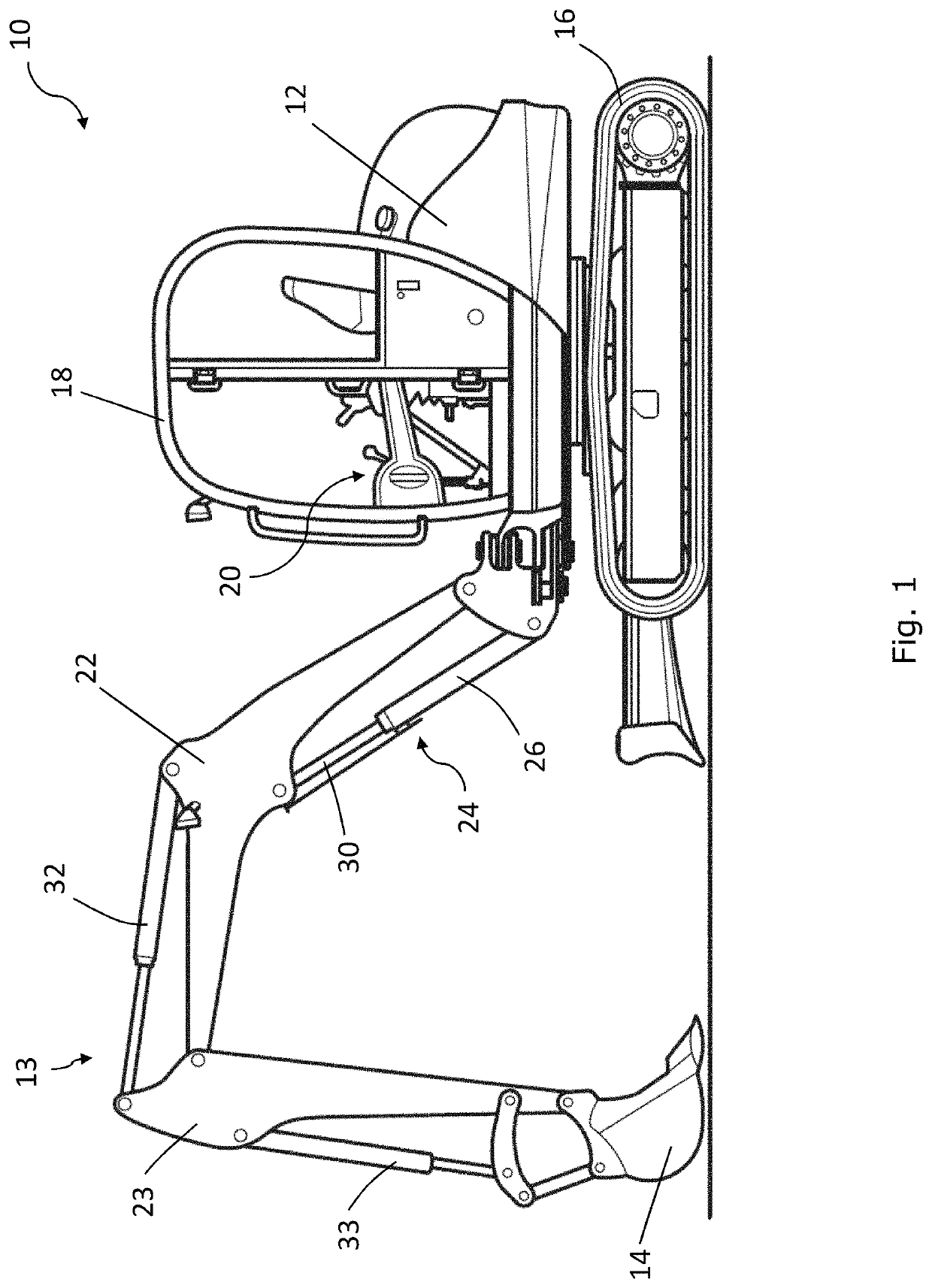
[0095]Referring to FIG. 1, a working machine according to an embodiment is indicated at 10. The working machine 10 has a chassis 12, a working arm 13 attached to the chassis 12, and an implement 14 connected to a free end of the working arm 13. In the illustrated embodiment, tracks 16 are provided to move the working machine 10. In alternative embodiments, wheels may be provided to move the working machine 10, instead of tracks 16.

[0096]The working machine 10 includes a cab 18 with a collection of controls 20 for moving the working arm 13, the tracks 16, or controlling other functions of the working machine 10.

[0097]The working arm 13 includes a boom 22 pivotally attached to the chassis 12, a dipper arm 23 pivotally attached to the boom 22, and an implement pivotally attached to the dipper arm 23. In the illustrated embodiment, the implement is a bucket 14, which is used for soil-shifting or materials handling operations (e.g. trenching, grading, and loading) and / or materials handli...


PUM


Abstract

A hydraulic system for a working machine, the hydraulic system includes: a hydraulic fluid reservoir; a boom actuator having an ascending chamber and a descending chamber; a first pump; a first directional control valve comprising a first ascending state configured for moving the boom in the ascending direction, a descending state configured for moving the boom actuator in the descending direction, and a first neutral state; a second pump; a second directional control valve comprising a second ascending state configured for moving the boom actuator in the ascending direction, and a second neutral state; wherein the second directional control valve further comprises a float state configured to connect at least one of the ascending and descending chambers to the hydraulic reservoir for permitting the boom to move freely in the descending and / or descending directions.

Description

FIELD OF THE INVENTION[0001]The present invention relates to a working machine, a hydraulic system for a working machine, and a method of operating a hydraulic system for a working machine.BACKGROUND OF THE INVENTION[0002]Various types of working machines are known for soil-shifting operations (e.g. trenching, grading, and loading) and materials handling (e.g. depositing aggregate in trenches, lifting materials and placing them on an elevated platform). Slew excavators are one example of such a working machine, which include a shovel at one end and a working arm arrangement at the other end.[0003]The working arm arrangement is used for manipulating an attachment, such as a bucket, to perform working operations of the types listed above. A prime mover drives a hydraulic pump, in order to provide hydraulic fluid to operate hydraulic actuators to control a function of the working machine, such as raising a boom of the working arm arrangement. Such hydraulic actuators typically have a b...

Claims


Application Information

Patent Timeline
Patent Type & Authority Patents(United States)
IPC IPC(8): E02F9/22
CPCE02F9/2217E02F9/2285E02F9/2292E02F9/2296E02F9/2203E02F3/325F15B11/0426F15B2211/20576F15B2211/7053F15B2211/3127F15B2211/329F15B2211/30515F15B2211/30565F15B2211/6313F15B2211/3058F15B2211/665F15B2211/20546F15B2211/6355F15B2211/355F15B2211/3111F15B2211/41581F15B2211/31582E02F9/2278E02F9/2282F15B11/04F15B11/042F15B2211/255F15B2211/31517F15B2211/31535F15B2211/7051F15B2211/7052E02F9/2267F15B13/021F16K31/18F15B2211/30525
Inventor ABELL, KYLE SCOTTGOODWIN, MARK ORTON
Owner J C BAMFORD EXCAVATORS LTD
Why Eureka
Try Eureka