Method for dynamically tuning the clock frequency of an oscillator and corresponding oscillating system

a technology of dynamic tuning and oscillator frequency, which is applied in the direction of generator stabilization, pulse automatic control, electric pulse generator, etc., can solve the problems of system failure, difficult to emphasize the importance of accurate oscillator frequency, and inacceptable dimensions for many applications, so as to minimize or reduce the error

Active Publication Date: 2008-02-21
STMICROELECTRONICS SRL
View PDF2 Cites 0 Cited by
  • Summary
  • Abstract
  • Description
  • Claims
  • Application Information

AI Technical Summary

Benefits of technology

[0011]An object of the present invention is providing an oscillator architecture that allows for minimizing or reducing the error E due to: the variation of the technological process, the variation of the temperature, and the variation of the supply voltage. Thereby, the oscillator system may be tuned through an electric magnitude signal, the electric magnitude signal being different from the frequency of the modulated output signal.

Problems solved by technology

However, although quartz oscillators may be characterized by good accuracy and a decrease in the final costs of the electronic device, they may have unacceptable dimensions for many applications.
Unfortunately, the characteristics and performance of an integrated oscillator may depend on the variations in the manufacturing technological process, the supply voltage variations, and the temperature variations.
At the end of the manufacturing process, it may be difficult to emphasize the importance of an accurate oscillator frequency, with respect to the optimum design frequency.
Overcoming the limit value at which the digital circuits can switch correctly, may cause a failure of the system.

Method used


Image

  • Method for dynamically tuning the clock frequency of an oscillator and corresponding oscillating system
  • Method for dynamically tuning the clock frequency of an oscillator and corresponding oscillating system
  • Method for dynamically tuning the clock frequency of an oscillator and corresponding oscillating system

Examples


Embodiment Construction

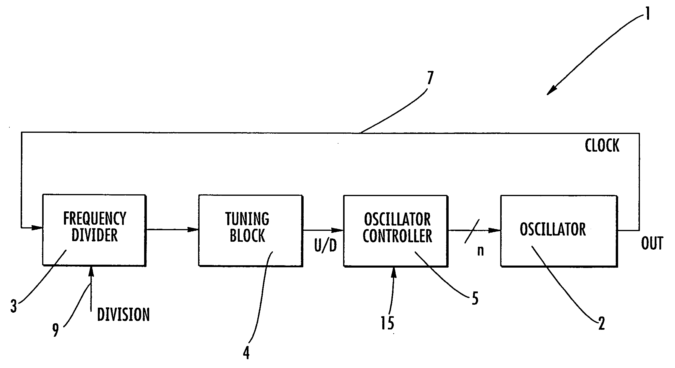
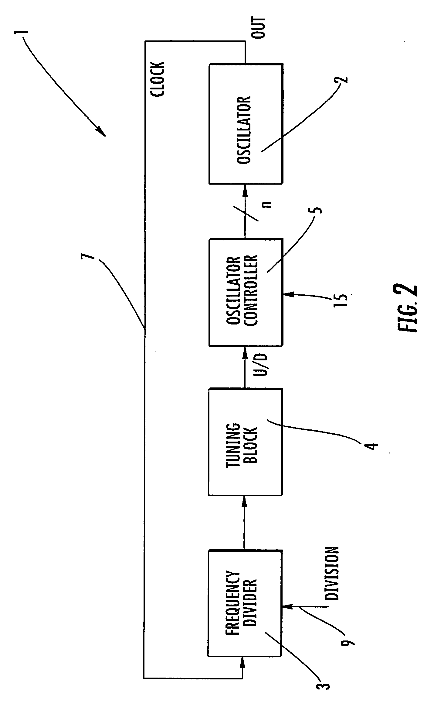
[0022]With reference to these Figures, and, in particular, to FIG. 2 that globally and schematically illustrates a configurable oscillator system realized according to an embodiment for obtaining a dynamic tuning of the timing / clock frequency produced at the output. This oscillator system 1 comprises an oscillator block 2, for example, of the type illustrated in FIG. 3, having a plurality n inputs receiving respective input signals (in1, in2, . . . inn) for producing, on a single output OUT, a clock signal.

[0023]The clock signal is fed into the input of a frequency divider block 3 by means of a feedback connection 7. The frequency divider block 3 receives, on an input, an enable signal 9 for carrying out a frequency division and outputs a frequency value divided by a predetermined factor. The frequency divider block 3 can be implemented, for example, with a counter with configurable maximum value, even if other alternative approaches can be adopted according to the needs of a partic...


PUM


Abstract

An oscillator system may include an oscillator block having a plurality of inputs and outputting a clock signal, a frequency divider block receiving the clock signal and outputting a divided clock signal, a tuning block receiving the divided clock signal and outputting a comparison signal, and a control block coupled to the tuning block. The control block may receive the comparison signal. The control block may include a configuration block for producing a plurality of outputs for the corresponding inputs of the oscillator block, and an Up / Down counter having outputs applied to the configuration block.

Description

FIELD OF THE INVENTION[0001]The present invention relates to a method for dynamically tuning a clock frequency emitted by an oscillator, and to an oscillator system comprising an oscillator block having a plurality of inputs and a clock signal output.BACKGROUND OF THE INVENTION[0002]As known in the relevant technical field, an electronic device may comprise a microprocessor, a state machine, or digital components, and may need a scanning or timing signal for evolving from one state to another. Within this context, it may be important to accurately regulate the frequency of this timing or clock signal to maximize the performance of the system.[0003]It is also known that dimensions and costs may be important aspects in the development of an electronic device. To the purpose of accurate regulation of the clock frequency, it may be suitable to use an oscillator of the integrated type, avoiding approaches comprising discrete components, such as, for example, quartz oscillators. However, ...

Claims


Application Information

Patent Timeline
Patent Type & Authority Applications(United States)
IPC IPC(8): H03K3/011H03K3/01
CPCH03J7/065H03L7/0991H03L7/093H03L7/02
Inventor AMATO, STEFANOMANNINO, FRANCESCOPICCA, MASSIMILIANOSCAPIN, MIRKO
Owner STMICROELECTRONICS SRL
Why Eureka
Try Eureka