
Reference voltage selection device and source driver device and display device using the same

a reference voltage selection and source driver technology, applied in the field of display devices, can solve the problems of increased cost, increased error generation, complex layout, etc., and achieve the effect of reducing or minimizing errors

Inactive Publication Date: 2006-07-13
NOVATEK MICROELECTRONICS CORP
View PDF2 Cites 2 Cited by
  • Summary
  • Abstract
  • Description
  • Claims
  • Application Information

AI Technical Summary

Benefits of technology

The present invention relates to a reference voltage selection device and a source driver device for a display device. The reference voltage selection device is designed to adjust the connection between basic reference voltages and the input terminals of a digital to analog converter, reducing errors between the actual brightness and the standard brightness of the display device. The source driver device includes a receiving device, a digital to analog converter, an output buffer, and a reference voltage selection device. The invention aims to improve the accuracy and reliability of display devices, particularly liquid crystal displays, by minimizing errors between the actual brightness and the standard brightness.

Problems solved by technology

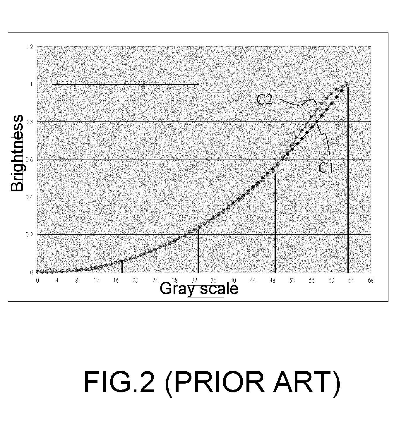
Generally, the error may be generated by the error of the device providing the set of the reference voltage.
However, the layout may be more complex and of large size, e.g., additional components such as operational amplifiers (generally, the output terminal of each reference voltage needs an operational amplifier) are required.
Therefore, the cost may be increased.
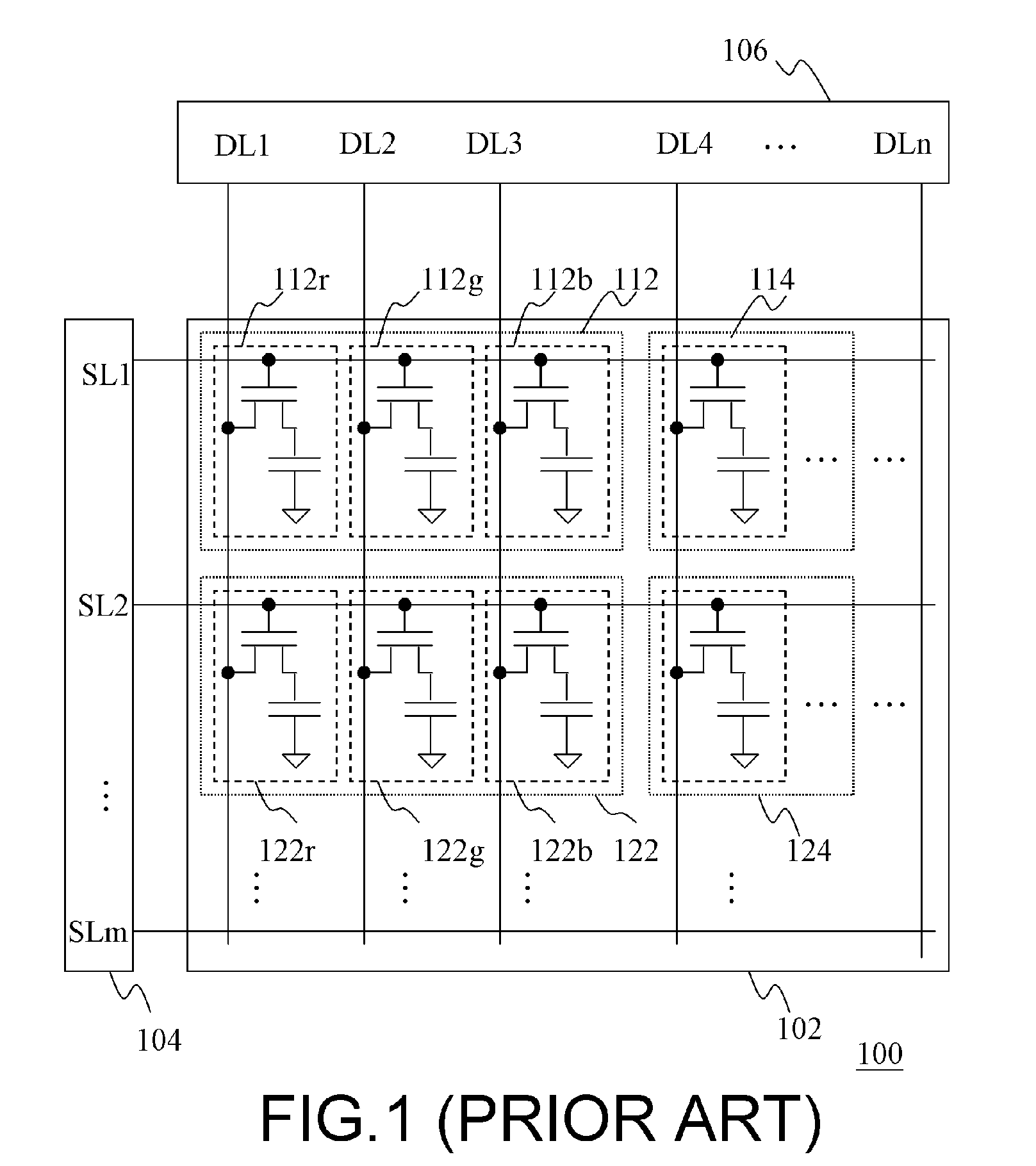
Therefore, if the design of the source driver 106 should be changed corresponding to the structure of the liquid crystal panel and the property of liquid crystal, the cost of manufacturing the chip is too high.

Method used


Image

  • Reference voltage selection device and source driver device and display device using the same
  • Reference voltage selection device and source driver device and display device using the same
  • Reference voltage selection device and source driver device and display device using the same

Examples


Embodiment Construction

[0035] The present invention now will be described more fully hereinafter with reference to the accompanying drawings, in which embodiments of the invention are shown. This invention may, however, be embodied in many different forms and should not be construed as limited to the embodiments set forth herein; rather, these embodiments are provided so that this disclosure will be thorough and complete, and will fully convey the scope of the invention to those skilled in the art. Like numbers refer to like elements throughout.

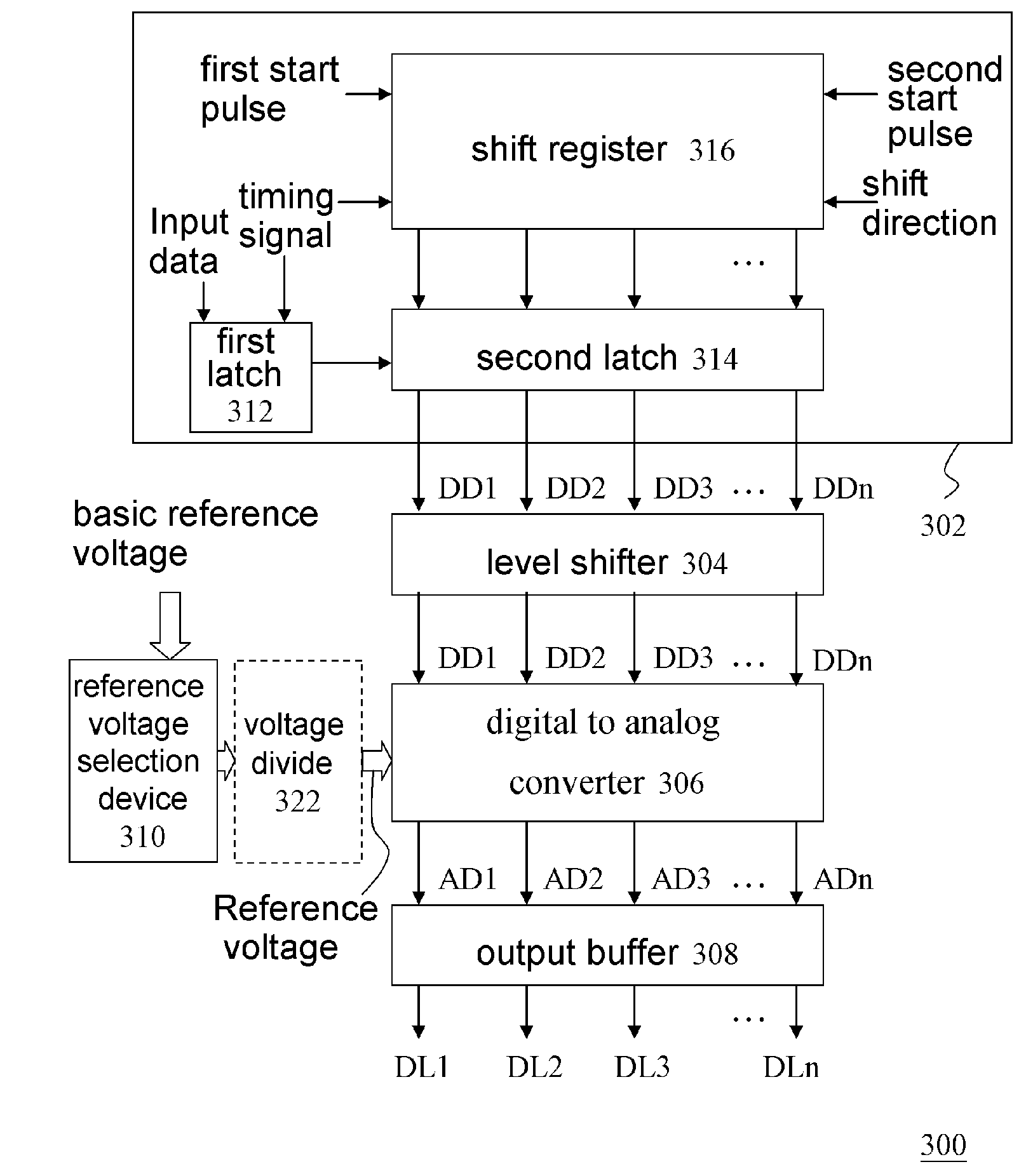
[0036]FIG. 3 is a schematic circuit block diagram of a source driver of a LCD panel according to one embodiment of the present invention. As shown in FIG. 3, a source driver 300 may comprise, for example, a receiving device 302, a level shifter 304, a digital to analog converter 306, an output buffer 308 and a reference voltage selection device 310. The receiving device 302 may be adopted for receiving and registering an input data (e.g., an input data input in se...


PUM


Abstract

A reference voltage selection device suitable for a display device comprising a digital to analog converter is provided. The digital to analog converter may include a plurality of input terminals and may be adopted for providing a displaying voltage to the display device. The selection device may include a reference voltage selector for receiving a plurality of basic reference voltages, wherein the reference voltage selector is suitable for selecting a relationship between the basic reference voltages and the input terminals to reduce an error between the displaying voltage and a predetermined standard voltage.

Description

CROSS-REFERENCE TO RELATED APPLICATION [0001] This application claims the priority benefit of Taiwan application serial no. 941 00436, filed on Jan. 7, 2005. All disclosure of the Taiwan application is incorporated herein by reference. BACKGROUND OF THE INVENTION [0002] 1. Field of the Invention [0003] The present invention relates to a display device. More particularly, the present invention relates to a source driver device of a display device. [0004] 2. Description of Related Art [0005] Recently, liquid crystal display (LCD) panel has gradually become the mainstream of display panel because of their advantageous features of light weight, compact size, suitable for large or small area application, low operation voltage, low power consumption, and radiation free. Especially, LCD panel is more applicable for portable electronic device such as the display of notebook, mobile phone, or personal digital assistance (PDA). Therefore, the LCD panel has become an indispensable device and i...

Claims


Application Information

Patent Timeline
Patent Type & Authority Applications(United States)
IPC IPC(8): G09G3/36
CPCG09G3/3688G09G2310/027
Inventor KAO, CHIEN-HSIEN
Owner NOVATEK MICROELECTRONICS CORP
Learn More