Security system interface module

a technology of security system and interface module, which is applied in the field of security system interface module, can solve the problems of the inability to detect the presence of a triggered alarm

Active Publication Date: 2008-02-21
NAPCO SECURITY SYST
View PDF7 Cites 201 Cited by
  • Summary
  • Abstract
  • Description
  • Claims
  • Application Information

AI Technical Summary

Benefits of technology

[0014]Briefly stated and in accordance with the preferred embodiment of the present invention, an alarm interface module is described that permits an alarm monitoring system to be operational through an existing wide area network (WAN) modem that is linked to an existing local area network (LAN) system wherein the alarm interface module has a first LAN port coupled to the LAN system, a second LAN port coupled to an output port of an alarm control panel of the alarm monitoring system,

Problems solved by technology

Regrettably, the burgeoning level of technology utilized in present security alarm systems has far outpaced the level of skill of most installers of such security alarm systems.
Of course, if the protected premises were in an isolated (or, conversely, an extremely noisy) environment, the triggered alarm sound would do little to prevent burglaries.
Additionally, in the earliest closed loop security alarm systems, false alarms were so prevalent, that even if an audible or visual indicator was activated based on an unauthorized intrusion, the visual and/or audible indicator was often ignored.
Alarm manufacturers eventually overcame this deficiency by creating systems that would also trigger a tamper alarm if the system was compromised by the disconnecting of the telephone.
However, all such existing systems require customized cameras, specialized software, additional network cards, and the like, to permit proper functioning.
The difficulty in achieving wide-spread acceptance of such internet-based security systems is due to both the lack of computer-based experience of installers to incorporate such technology and the reluctance on the part of customers to have installers modify their computer or compute

Method used


Image

  • Security system interface module
  • Security system interface module
  • Security system interface module

Examples


Embodiment Construction

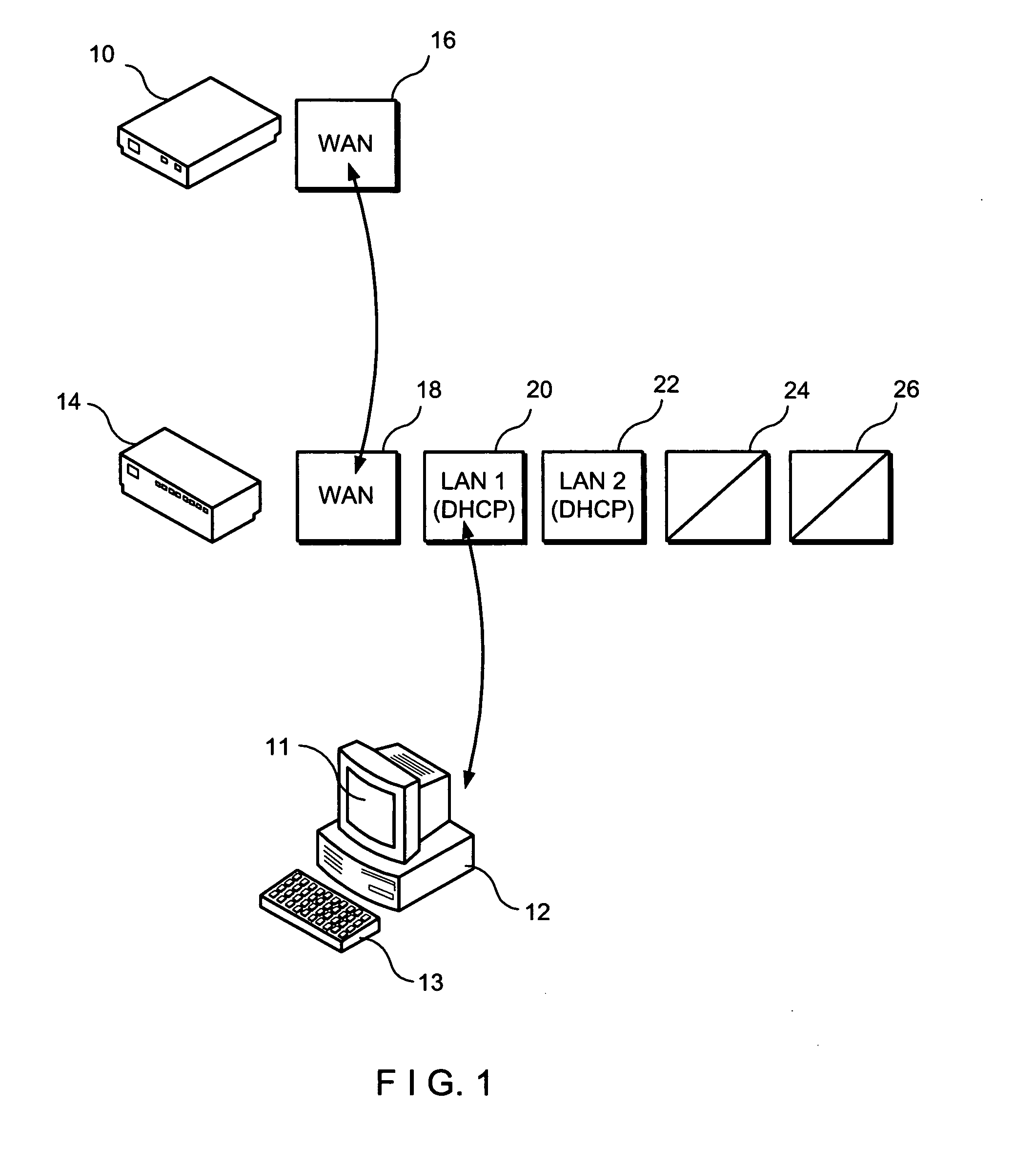
[0021]Referring first to FIG. 1, a modem 10, a personal computer 12, and a security interface module 14 are shown. Modem 10 has a WAN port 16 connected to a WAN port 18 of security interface module 14. Personal computer 12 is connected to a LAN port 20 of security interface module 14.

[0022]It should be noted by those skilled in the art that modem 10 can be comprised of any broadband modem such as a cable modem, a DSL line, etc. Moreover, as described in this specification, personal computer 12 can be any type of processing means including a MACINTOSH computer, a UNIX device, etc. While personal computer 12 has been shown to have a monitor 11 and a keyboard 13, such features are not necessarily required or can take different shapes. Typically, personal computer 12 is defined as being part of the LAN system and modem 10 is defined as being part of the WAN system.

[0023]LAN port 20 and a supplemental LAN port 22 (which is illustrated in FIG. 1 as not being connected to any other device)...


PUM


Abstract

An alarm interface module is described that permits an alarm monitoring system to be operational through an existing wide area network (WAN) modem that is linked to an existing local area network (LAN) system wherein the alarm interface module has a first LAN port coupled to the LAN system, a second LAN port coupled to an output port of an alarm control panel of the alarm monitoring system, a WAN port coupled to the WAN modem, and programming means capable of recognizing an identifying address dynamically assigned to the alarm control panels to route data from a remote alarm server to the alarm control panel while also permitting data communications to said LAN system from said WAN modem that are not initiated from the remote alarm server. The security system interface module of the present invention can be used with any security alarm panels, sensors, video devices, etc.

Description

FIELD OF THE INVENTION[0001]This invention is generally directed to a “plug-and-play” or, more accurately, a “plug-and-leave” security interface module for connecting a security alarm system to an existing computer system that utilizes a broadband modem. Specifically, the security interface module of the present invention can be installed without the need for modifying the software configuration of the computer and without the need for incorporating any additional hardware or firmware into the computer. Thus, the security interface module of the present invention permits a security installer to connect any type of security monitoring system comprising various types of alarm sensors, or a video monitoring system comprising various types of video monitoring cameras to an existing internet-based computer without the need for any specialized training in Transmission Control Protocol / Internet Protocol (TCIP / IP) technology or networking expertise. Moreover, in video applications, no custo...

Claims


Application Information

Patent Timeline
IPC IPC(8): G08B1/00H04N7/18G08B13/00
CPCG08B13/19656H04L67/125H04L63/1408G08B25/085
Inventor HEVIA, JORGECARRIERI, MICHAELKARL, THOMASCOLUCCIELLO, JOSE
Owner NAPCO SECURITY SYST
Why Eureka
Try Eureka