Timer reset circuit for overcurrent protection of switching power amplifier

a technology of switching power amplifiers and protection circuits, which is applied in the direction of amplifier protection circuit arrangements, amplifiers with semiconductor devices/discharge tubes, amplifiers, etc., can solve the problems of power loss, power loss, and additional bulky heatsinks attached to power amplifiers

Inactive Publication Date: 2008-02-21
PANASONIC SEMICON ASIA PTE +1
View PDF7 Cites 24 Cited by
  • Summary
  • Abstract
  • Description
  • Claims
  • Application Information

AI Technical Summary

Benefits of technology

[0018]According to the present invention, a method for allowing Class D circuit to return to normal operation automatically when overcurrent condition is no longer satisfied comprising:
[0019]generating a logic high control signal when either the current flowing through first MOSFET switch is higher than a reference level or the current flowing through second MOSFET switch is higher than a reference level or both; and
[0020]generating a logic high reset signal to deactivate control signal after the control signal is activated for a predetermined time period.
[0021]According to the present invention, an apparatus for allowing Class D circuit to return to normal operation automatically when overcurrent condition is no longer satisfied comprising:
[0022]a SR latch operative to output a logic high signal if OR gate outputs a logic high signal; and
[0023]a timer circuit operative to output a logic high signal after the logic high signal at the input of this timer circuit lasts for a predetermined time period.

Problems solved by technology

However, the Class AB push-pull amplifiers are very inefficient and can only achieve an efficiency of about 60%, which results in not only power loss, but also additional bulky heatsink attached to the power amplifiers.
Excessive current flows in either first MOSFET switch M1104 or second MOSFET switch M2105 or both, which is likely to cause damage to the amplifier circuit.
One disadvantage of above conventional overcurrent protection circuit is that upon the activation of control signal SD in case of overcurrent, first MOSFET switch M1104 and second MOSFET switch M2105 are in off state even if the overcurrent condition is no longer satisfied, for example, load short is cleared.

Method used


Image

  • Timer reset circuit for overcurrent protection of switching power amplifier
  • Timer reset circuit for overcurrent protection of switching power amplifier
  • Timer reset circuit for overcurrent protection of switching power amplifier

Examples


Embodiment Construction

[0028]The following description explains the best mode embodiment of the present invention.

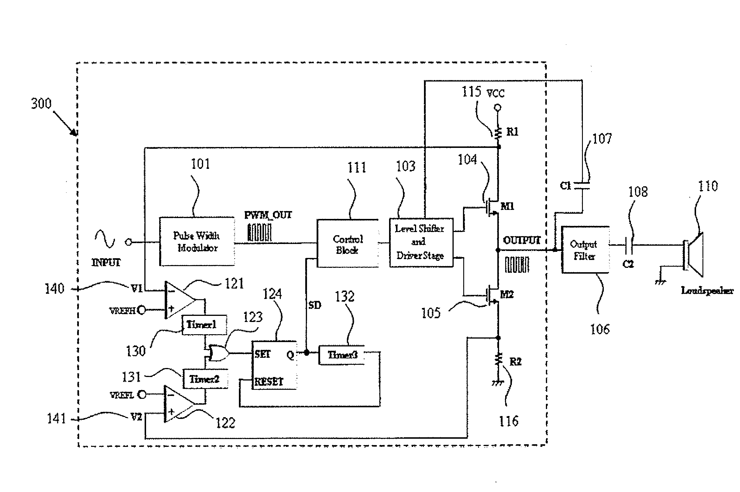
[0029]Referring to FIG. 3, a typical Class D system and overcurrent protection circuit with timer reset circuit according to the present invention is shown.

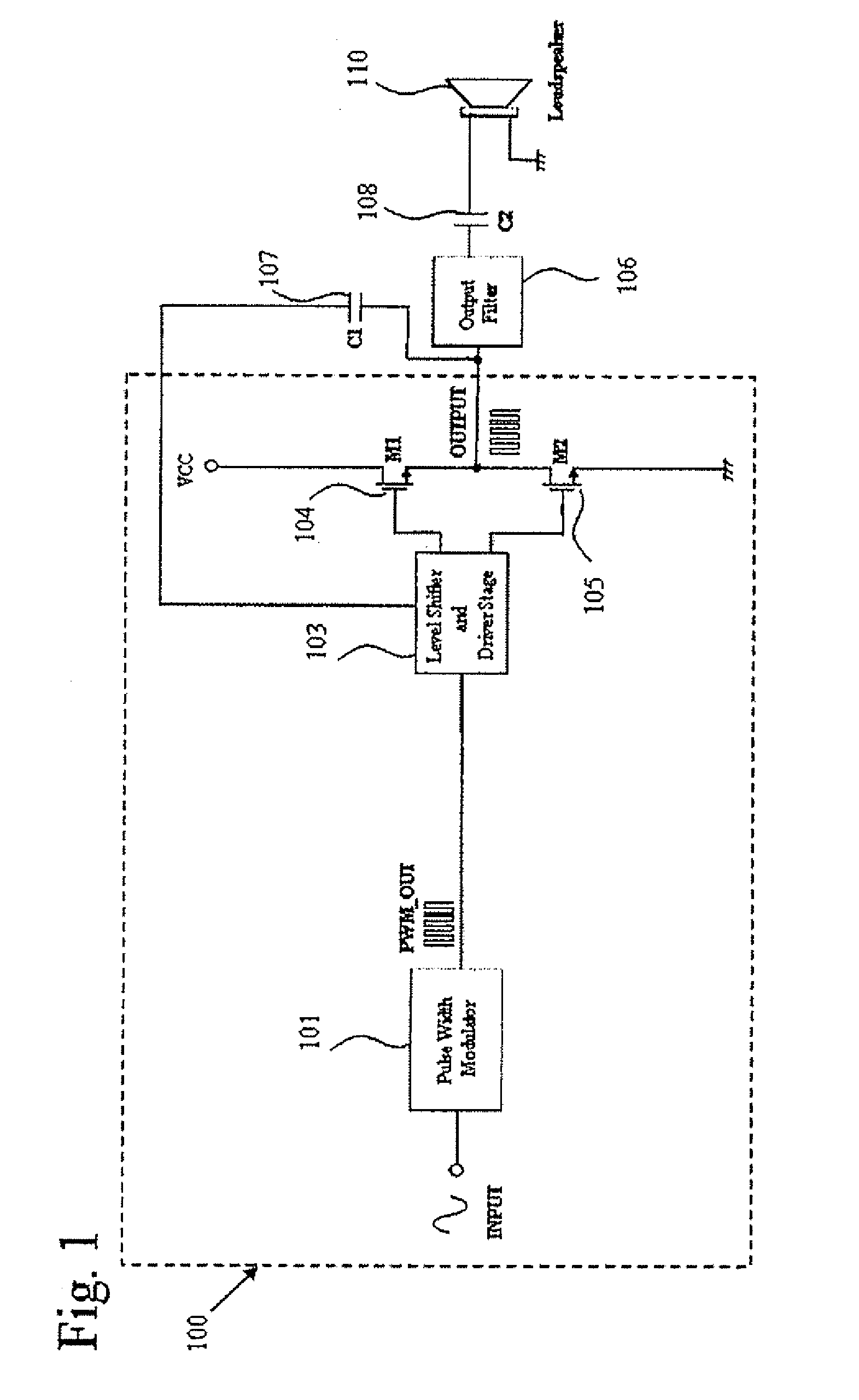
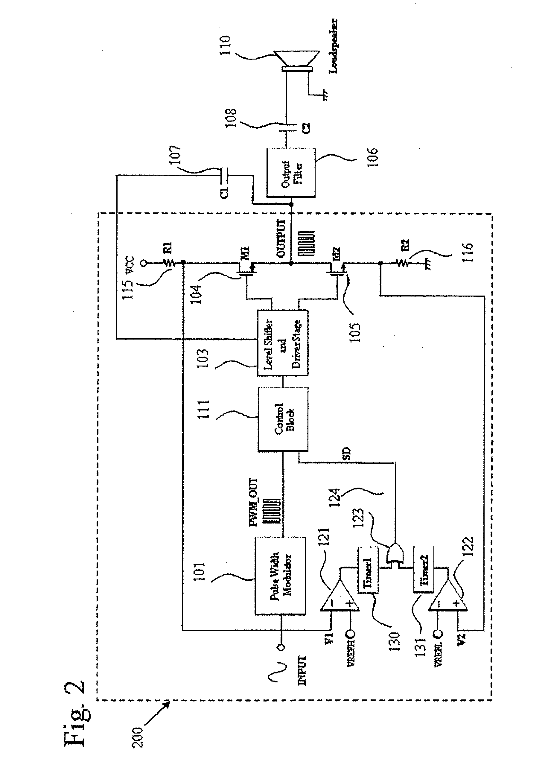
[0030]A typical Class D system has a pulse width modulator 101, a level shifter and driver stage 103, a first MOSFET switch M1104, a second MOSFET switch M2105. The overcurrent protection circuit with timer reset circuit has a first current detection resistor R1115, a second current detection resistor R2116, a first comparator 121, a second comparator 122, a timer 1 circuit 130, a timer 2 circuit 131, an OR gate 123, a SR latch 124, a control block 111 and a timer 3 circuit 132.

[0031]Here a first MOSFET switch M1104 and a second MOSFET switch M2105 are used, but can be any other type, such as N-type DMOS transistors, bipolar power transistors.

[0032]In normal operation, there is neither load short to ground nor load short to power supply nor...


PUM


Abstract

A smart overcurrent protection circuit is introduced. In case of successive current due to certain malfunctions flows in power transistor of a switching circuit a control signal is activated to stop power transistor switching. When overcurrent condition is no longer satisfied, the switching circuit is still able to return to normal operation.

Description

BACKGROUND OF THE INVENTION[0001]The present invention relates to a protection circuit for a switching power amplifier or a switching regulator and, more particularly, to a protection circuit for protecting the output stage of a switching circuit from destruction due to overcurrent from or to the load.[0002]Most of the audio power amplifiers in the market are based on Class AB amplifier. This architecture offers very good total harmonic distortion plus noise (THD+N) performance, with fairly low quiescent current. However, the Class AB push-pull amplifiers are very inefficient and can only achieve an efficiency of about 60%, which results in not only power loss, but also additional bulky heatsink attached to the power amplifiers.[0003]One major advantage of Class D amplifiers is the efficiency, which could reach above 90%. The high efficiency is achieved by full signal swing at power transistors. A typical Class D amplifier circuit 100 in FIG. 1 includes pulse width modulator 101, le...

Claims


Application Information

Patent Timeline
Patent Type & Authority Applications(United States)
IPC IPC(8): H02H3/00
CPCH03F3/217H03F1/52
Inventor WONG, SHIAH SIEWSUN, JING
Owner PANASONIC SEMICON ASIA PTE
Why Eureka
Try Eureka