Chassis partition architecture for multi-processor system

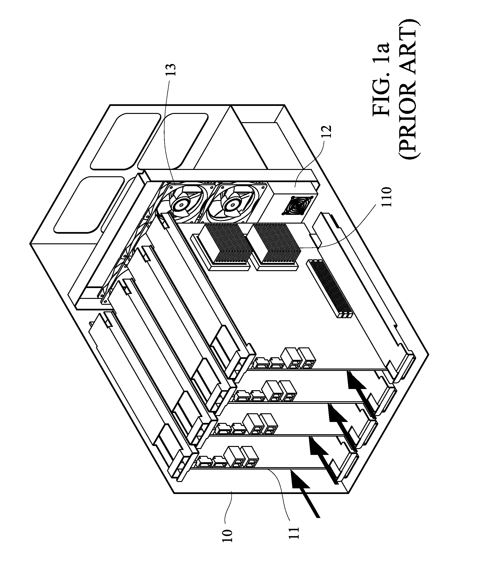
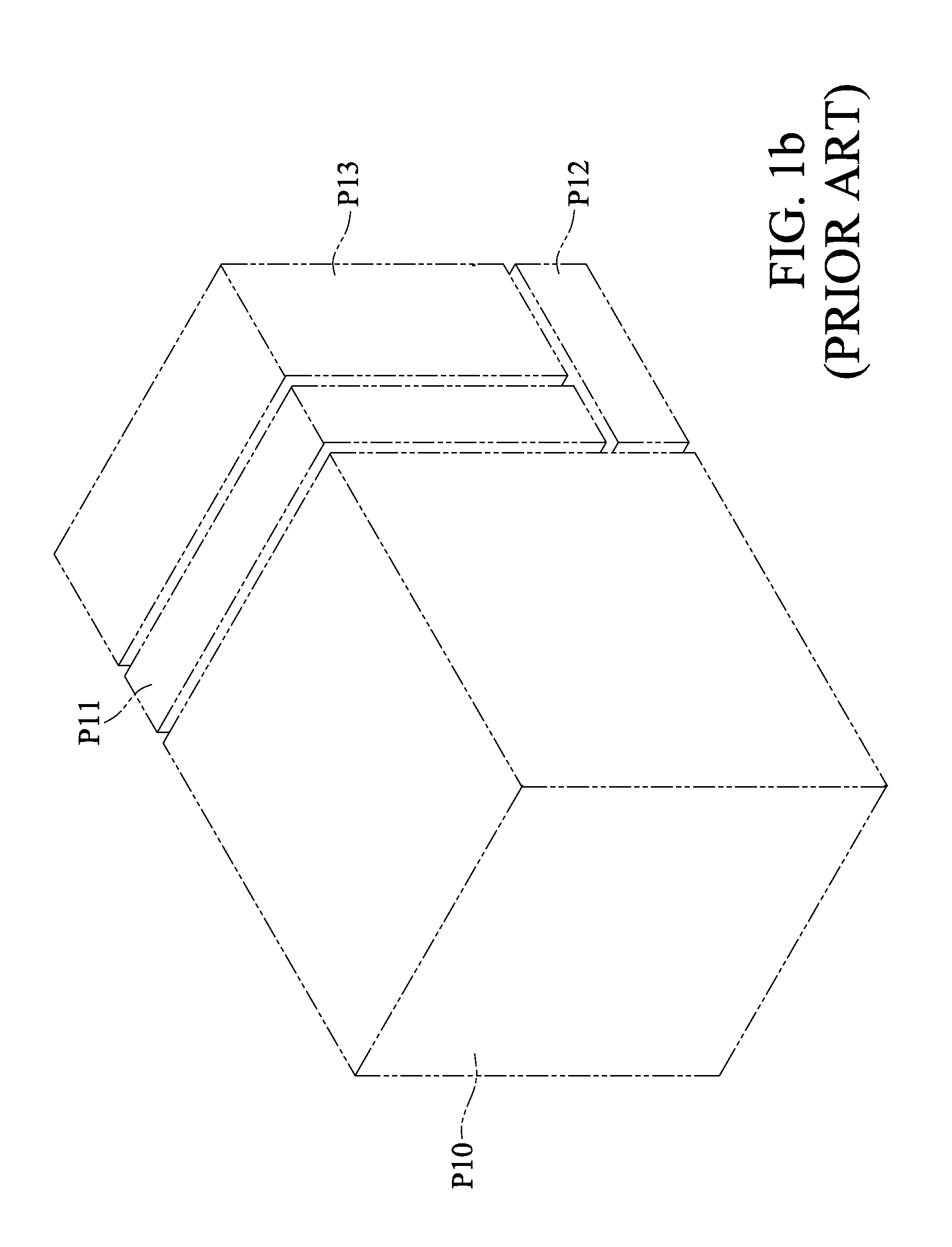
a multi-processor system and partition architecture technology, applied in the direction of electrical apparatus construction details, instruments, casings/cabinets/drawers, etc., can solve the problems of increasing the complexity of the system design, enclosures require a complex and expensive internal chassis, and the space arrangement of the chassis is always a significant issu

Inactive Publication Date: 2008-02-21
MITAC INT CORP
View PDF5 Cites 59 Cited by
  • Summary
  • Abstract
  • Description
  • Claims
  • Application Information

AI Technical Summary

Benefits of technology

[0017]In an embodiment of the present invention, the architecture further includes a main space and an sub-space, each provided with a dedicated airflow; wherein the main space includes the node partition and the expansion partition and the sub-space includes the function partition. In some cases, the main space further includes a main-fan partition located right in front of the node partition for containing one or more main system fan. The main space may further include a storage partition located behind the node partition and on the top of the expansion partition for containing several hard drives. On the other hand, the sub-space may further include a sub-fan partition located behind the function partition for containing one or more auxiliary system fan. In certain conditions, the sub-space may further include a power partition located behind the sub-fan partition for containing some power supplies.

Problems solved by technology

Chassis space arrangement is always a significant issue for computing systems.
For a multi-processor system with processors configured on plural printed circuit boards, traditional design of electronic enclosure requires a complex and expensive internal chassis with many routed cables therein to provide mechanical support for the electronic components.
The requirements for variable types of input / output devices and storage unit, including hot swapping plus airflow for cooling, further increase the complexity of the system design.
This complexity increases the overall sides of the system and in some cases limits some configurable options to become part of the “base architecture”, which is dictated by the overall dimensions of the chassis and internal structure.
One example is the difficulty in servicing the center interconnecting plane.
Most backplane and mid-plane designs in the prior art are not field serviceable due to difficulty or no access in the assembled chassis.
Another example is the difficulty to provide sufficient cooling and airflow to the various components due to blockage as a result of the placement of the different parts of the system.
Besides, once numerous function cards need to be configured on the system, it becomes much more difficult to fulfill the requirements of cooling, serviceability and hardware reliability.
For high-end systems, flexibility will be another critical issue.
Theoretically the more the subsystem boards are divided, the higher the system flexibility will be; however, the physical division is still limited by actual hardware capabilities.
The cooling problem in such “flat” system is that the sizes of the fans 35 is relatively smaller, which require high rotation speed to carry away the heat efficiently.
However, the higher the fan speed increases, the more the fan noise occurs.
Besides, although such system has overall two or three serviceable / configurable sides (the two lengthwise sides and the top side), the cooling, serviceability and reliability problems will still occur when extra function cards (not shown) are added on the system architecture.
When a lot more expansion cards or functions cards are required, the chassis partition will become much more complicated.
Besides, the flow paths will be too long to dissipate heat efficiently.
Plus the arrangement of blockage units like hard drives, the architecture becomes extremely complicated.

Method used


Image

  • Chassis partition architecture for multi-processor system
  • Chassis partition architecture for multi-processor system
  • Chassis partition architecture for multi-processor system

Examples


Embodiment Construction

[0030]To achieve outstanding serviceability, configurability and cooling performance of a multi-processor system, a partition-oriented chassis design according to the present invention is provided under some hardware limitations.

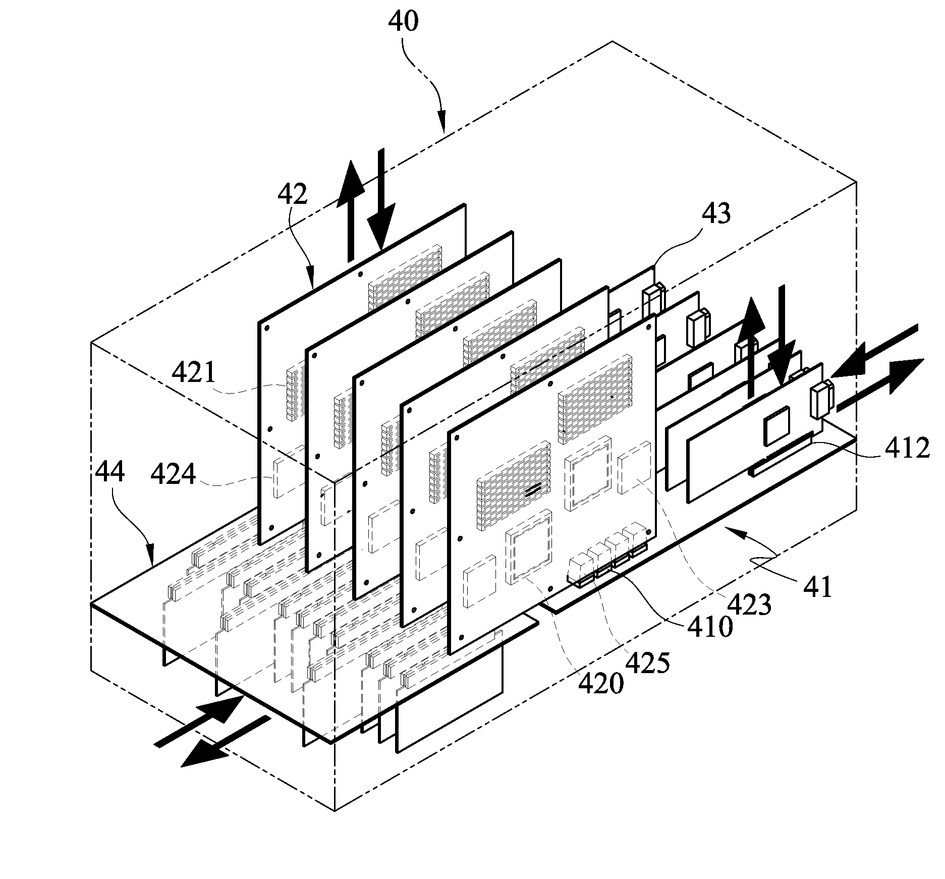
[0031]Please refer to FIGS. 4a and 4b. A partition architecture of a chassis 40 according to an embodiment of the present invention mainly includes a node partition P411, a expansion partition 412 and a function partition 421. Such partition architecture is designed dedicatedly for a multi-processor system with plural boards and numerous cards shown in FIG. 4b. The term “partition” herein is defined as an internal space of the chassis with no limitations to the mechanical construction.

[0032]The multi-processor system mainly includes a chassis 40, a bottom plane 41, plural processor boards 42, plural expansion cards 43, a function board 44 and plural function cards 45 and 46.

[0033]Basically, the node partition P411 is located at a middle section of the chassi...


PUM


Abstract

A chassis partition architecture of a chassis for configuring a multi-processor system is provided to fulfill flexibility, serviceability and configurability of a multi-processor system. The partition architecture mainly includes the partition architecture mainly includes a node partition, a expansion partition and a function partition. The node partition is located at a middle section of the chassis, mainly for containing several processor boards that are configured vertically and lengthwise. The expansion partition is located behind the node partition, mainly for containing several expansion boards that are configured vertically and lengthwise. And the function partition is located at a front section of the chassis lower than the node partition and the expansion partition, mainly for containing a plurality of function cards that are configured upside-down vertically and lengthwise.

Description

BACKGROUND OF THE INVENTION[0001]1. Related Applications[0002]This application is a non-provisional application of the U.S. provisional application Ser. No. 60 / 822,543 to Lee et al., entitled “Highly Compact, Integrated, Modular Computer Design with All Serviceable Parts without Internal Cables and Improved Cooling” filed on Aug. 16, 2006.[0003]2. Field of Invention[0004]The present invention relates to chassis space arrangement of electrical apparatus, and more particularly, to a chassis partition architecture for a multi-processor system.[0005]3. Related Art[0006]Chassis space arrangement is always a significant issue for computing systems. Generally, physical hardware architecture determines space arrangement of the chassis. And oppositely the chassis needs to provide necessary mechanical supports for all the electrical units and modules involved in the computing system. Therefore, well-designed hardware architecture always accompanies with a corresponding chassis that has excell...

Claims


Application Information

Patent Timeline
Patent Type & Authority Applications(United States)
IPC IPC(8): H05K7/00H02B1/00G06F1/16H05K5/00
CPCG06F1/185H05K7/1445G06F1/20G06F1/187
Inventor LEE, MARIO J.D.HIRAI, TOMONORIJONG, JYH MING
Owner MITAC INT CORP
Why Eureka
Try Eureka