
Auxiliary reaction frame system for cantilevered jack-up rigs, and method therefore

a technology of reaction frame and cantilever, which is applied in the direction of drilling rods, drilling pipes, artificial islands, etc., can solve the problems of limited operation and reduced drilling load availabl

Active Publication Date: 2008-02-21
LEFEBVRE MAXIME H
View PDF20 Cites 18 Cited by
  • Summary
  • Abstract
  • Description
  • Claims
  • Application Information

AI Technical Summary

Benefits of technology

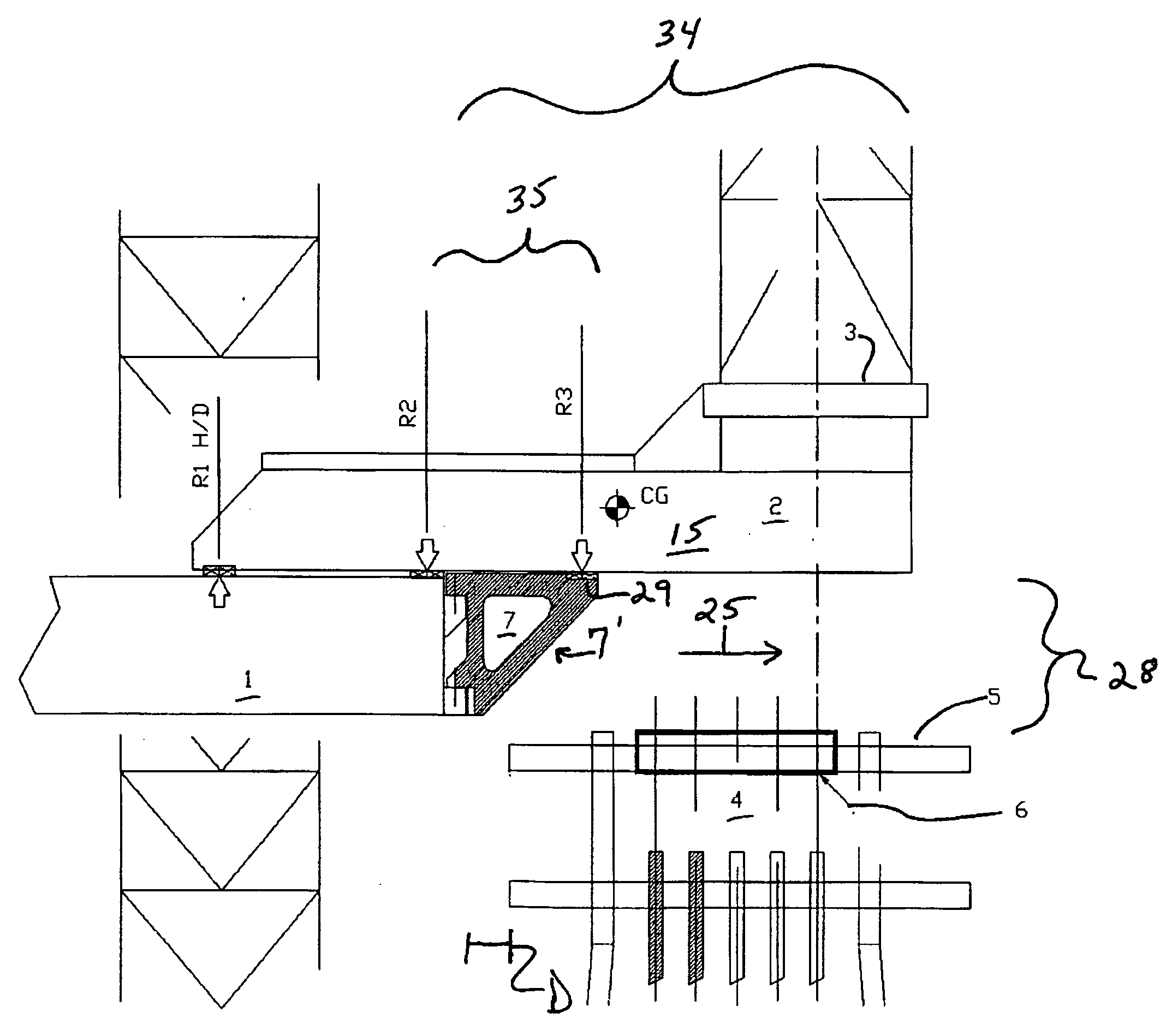
[0009]Another object of the present invention is to provide additional supports mounted on the transom along the cantilever beam path so as to sustain positive reaction, provide additional support, and thereby improve the cantilever rated load charts.
[0012]By the present invention, the new reaction added to the cantilever support arrangement has a primary purpose of increasing the rated capacity of the cantilever beams on the farther outreaches of the drilling envelope. The rating is improved by reducing the overhanging extent of the beams, where the bending effort of the cantilever beam is reduced by the same ratio.
[0016]When the tensioning is provided from the cantilever beams the drilling operation for exploration becomes more flexible because the conductor tensioning is possible along the entire length of the drilling envelope. In addition, when exploration drilling is possible further away from the transom, more valuable deck space is made available because the cantilever leaves more of the main deck exposed.

Problems solved by technology

A major limitation with oil well drilling or work over activities involving jack-up units utilizing a platform jacket and cantilever beam is the reduced drilling load available, due to the outreach position of said cantilever beams.
Accordingly, the reduced drilling loads impose limitations on operations, the greater extent maximum drilling load being achievable only within the pre-established drilling envelope.

Method used


Image

  • Auxiliary reaction frame system for cantilevered jack-up rigs, and method therefore
  • Auxiliary reaction frame system for cantilevered jack-up rigs, and method therefore
  • Auxiliary reaction frame system for cantilevered jack-up rigs, and method therefore

Examples


Embodiment Construction

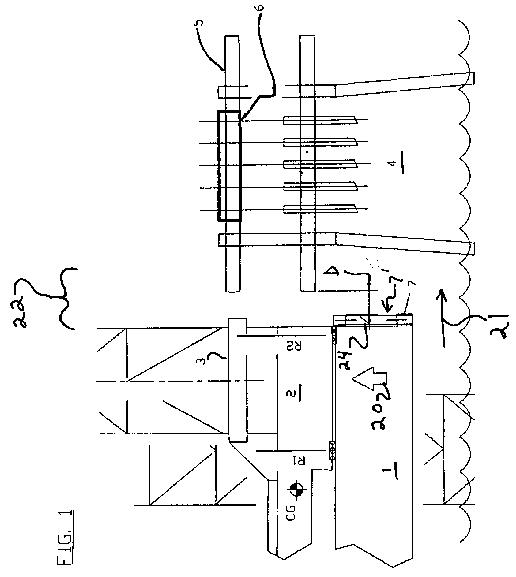
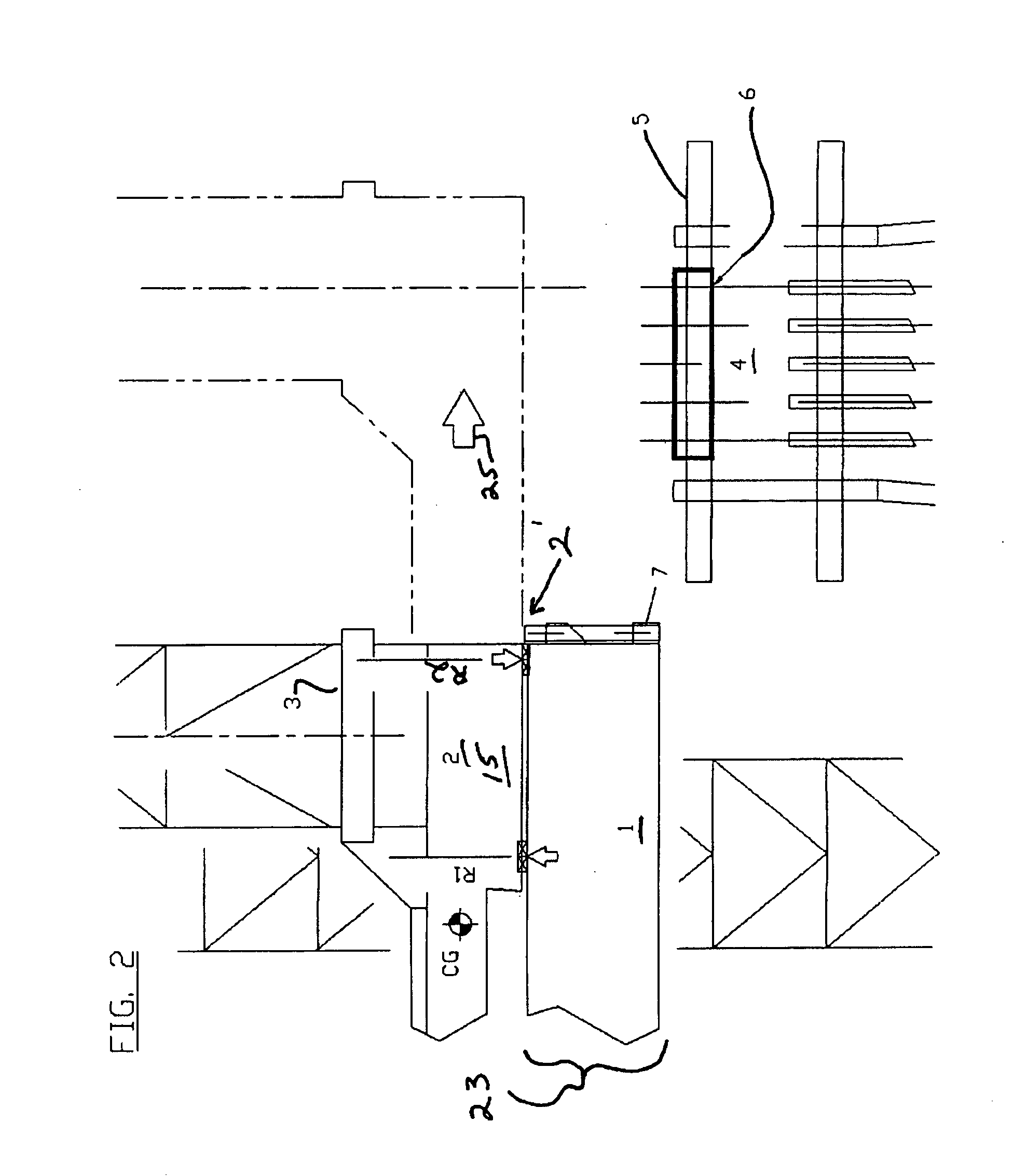
[0030]The preferred embodiment of the present invention, contemplating a selectively deployable (i.e., retractable) reaction frame for self-elevating platforms utilizing cantilever beams, is described below with reference to the Figures. The utilization and deployment process of the present invention, as utilized in conjunction with a drilling unit, is also illustrated and discussed in detail, herein.

[0031]Referring to FIGS. 1 and 2, a self elevating drilling unit comprising, for example, a jack up vessel 1 (also known as a jack up rig) is positioned 21 (for example, 5-10 feet, with the distance varying depending upon operator skills, soil, the vessel deployed, etc) so as to be situated adjacent 22 to a platform jacket 4, then elevated 20 to working position 23. First 7 and second 7′ reaction frames associated with the stern of the vessel are shown in their retracted 24 position, said frames mounted at the transom 11 of the jack up vessel 1.

[0032]As shown, in the retracted position ...


PUM


Abstract

A retractable stern reaction frame for reinforcing self elevating platform cantilever beams. The preferred embodiment contemplates a support framework mounted on a self elevating platform transom and positioned to engage the cantilever to project the reaction point farther towards the cantilever reach. The frameworks are to be retractable (or portable) to allow the self elevating unit to position itself closer to the jackets than would otherwise be possible. The framework is designed to transmit the reaction forces back to the main deck, cantilever support bulkheads, inner bottom and bottom structure.

Description

BACKGROUND OF THE INVENTION[0001]1. Field of the Invention[0002]The present invention relates to structural supports, and particularly to a system for selectively enhancing the support configuration of cantilever beams on jack-up drilling units or the like.[0003]2. Description of the Relevant Art[0004]A major limitation with oil well drilling or work over activities involving jack-up units utilizing a platform jacket and cantilever beam is the reduced drilling load available, due to the outreach position of said cantilever beams.[0005]In such systems, the drill-floor that carries the drilling derrick is typically supported by 2 independent beams via a substructure that forms the cantilever assembly. The drill-floor skids transversely, to reach the drilling template ports, and as a result of this movement, the drilling load is applied unequally on the two cantilever beams. Thus, maximum outreach and offset of the drill-floor are dictated by the allowable load limits of the beams.[000...

Claims


Application Information

Patent Timeline
IPC IPC(8): E02B17/00
CPCE02B17/0004E21B19/004E02B17/04E02B17/021
Inventor MORRISON, MARVIN LYNNLEFEBVRE, MAXIME HUGUES
Owner LEFEBVRE MAXIME H
Learn More