
Collision prediction and mitigation method for a vehicle

a technology for predicting collisions and vehicles, applied in vessel construction, steering initiations, instruments, etc., can solve problems such as system initiating actions, false alarms, and tendency to overstate the turning and braking capability of vehicles, so as to optimize collision mitigation and optimize collision mitigation

Inactive Publication Date: 2008-02-21
DELPHI TECH INC
View PDF5 Cites 37 Cited by
  • Summary
  • Abstract
  • Description
  • Claims
  • Application Information

AI Technical Summary

Benefits of technology

The present invention is a method for predicting and avoiding collisions in vehicles. It takes into account the vehicle's ability to avoid collisions and optimizes the process. The method estimates the time it takes to stop or turn and calculates the time it takes to collide. If the estimated time is greater than the calculated time, the collision is considered unavoidable. The method also takes into account the vehicle's braking process and automatically initiates pre-charging of the brakes when needed to optimize collision mitigation. Overall, this method improves the accuracy and effectiveness of predicting and avoiding collisions in vehicles.

Problems solved by technology

A concern associated with collision predicting systems, particularly those that initiate collision avoidance or collision mitigating actions, is the potential for false alarms—that is, a situation in which the system initiates an action prematurely or unnecessarily.
For this reason, there is a tendency to overstate the vehicle's turning and braking capability.
However, this will severely limit the effectiveness of the system in situations where the vehicle is traveling on a low coefficient-of-friction surface such as a snowy or icy road.

Method used


Image

  • Collision prediction and mitigation method for a vehicle
  • Collision prediction and mitigation method for a vehicle
  • Collision prediction and mitigation method for a vehicle

Examples


Embodiment Construction

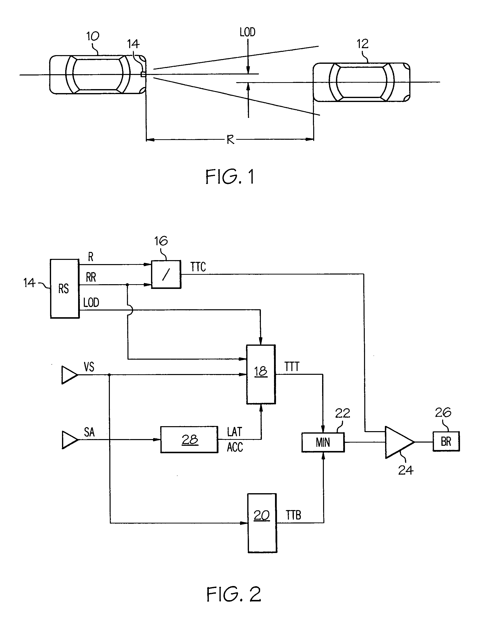
[0008]The diagram of FIG. 1 depicts a host vehicle 10 and a target vehicle or other obstacle in the forward path of the host vehicle 10. The host vehicle 10 is equipped with a system including a radar ranging sensor 14 for carrying out the collision prediction and mitigation method of the present invention. The host vehicle 10 is moving in the direction of the target vehicle 12, which may be moving or stationary. The ranging sensor 14, which may also be used for other vehicular applications such as adaptive cruise control, provides three parameters of interest: range R, range-rate RR, and lateral offset distance LOD. The range and lateral offset distance parameters R and LOD are designated in the illustration of FIG. 1; the range-rate parameter RR is the closing velocity, or the velocity of the host vehicle 10 relative to that of the target vehicle 12. In addition to the ranging sensor 14, the host vehicle 10 is equipped with a vehicle speed sensor and a turning sensor such as a ste...


PUM


Abstract

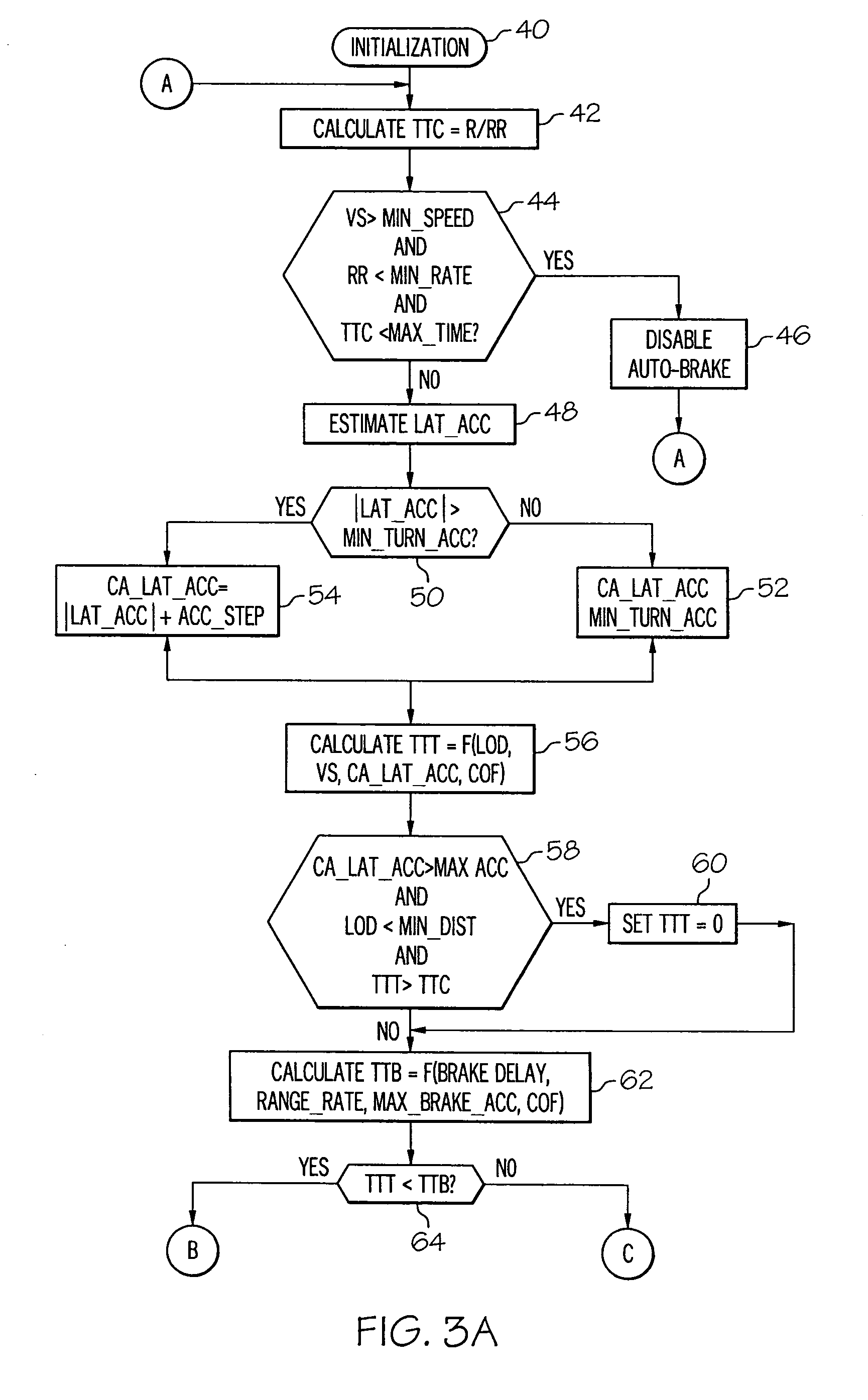
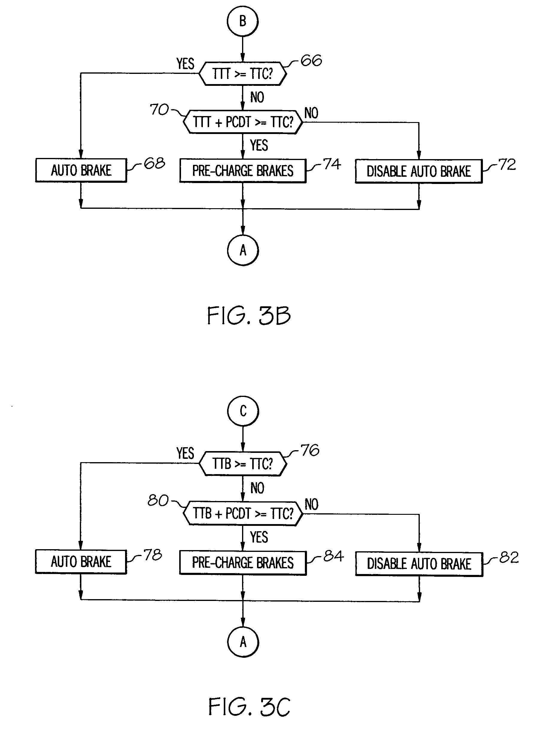
A potential collision is predicted by comparing estimates of the time-to-brake (TTB) and the time-to-turn (TTT) of a host vehicle with a computed time-to-collision (TTC). The collision is deemed to be unavoidable when the smaller of TTB and TTT is greater than TTC. The TTT estimate is based in part on the lateral acceleration capability of the vehicle, and the lateral acceleration is initialized to a low value corresponding to its instantaneous capability, and is set incrementally higher than the actual lateral acceleration when the driver initiates evasive turning. The TTT and TTB estimates are increased by the time required to pre-charge the vehicle brakes so that brake pre-charging can be automatically initiated when required to optimize collision mitigation due to braking.

Description

TECHNICAL FIELD[0001]The present invention relates to collision prediction for a motor vehicle, and more particularly to a prediction and mitigation method that takes into account the dynamic collision avoidance capability of the vehicle.BACKGROUND OF THE INVENTION[0002]It has been proposed to install a forward-looking radar or other ranging sensor on a vehicle for purposes of collision sensing. Various collision avoidance or collision mitigating actions can be taken depending on the imminence of a potential collision event. Such actions include, for example, warning the driver, initiating or maximizing braking, and arming or even deploying supplemental restraints for passenger protection. For example, the U.S. Pat. No. 6,084,508 to Mai et al. initiates emergency braking of a vehicle when it is determined that a collision with a detected obstacle can no longer be avoided by steering corrections or braking. A collision is deemed to be unavoidable according to Mai et al. when the targ...

Claims


Application Information

Patent Timeline
Patent Type & Authority Applications(United States)
IPC IPC(8): B62D11/00G06F19/00
CPCB60T2201/024B60T7/22
Inventor WEAVER, RICHARD A.WIDMANN, GLENN R.TURNER, DOUGLAS D.
Owner DELPHI TECH INC
Learn More