Bell cup cleaning system and method

a cleaning system and bell cup technology, applied in the direction of cleaning process and apparatus, burners, electrostatic spraying apparatus, etc., can solve the problems of requiring the shutdown of coating operation, affecting the quality of coating, and slow manual cleaning by probing, etc., to achieve fast and efficient process, reduce the effect of manufacturing and assembly process, and reduce the time required

Inactive Publication Date: 2008-02-28
ILLINOIS TOOL WORKS INC
View PDF8 Cites 5 Cited by
  • Summary
  • Abstract
  • Description
  • Claims
  • Application Information

AI Technical Summary

Benefits of technology

[0012]An advantage of the present invention is providing a cleaning system and method for a rotary atomizing applicator that cleans the fluid nozzles and passageways, the inner surface and the outer surface of the bell cup in a fast, efficient process requiring minimal time.
[0013]Another advantage of the present invention is providing a bell cup cleaning system and method that can be performed and operated between applicating steps without slowing manufacture and assembly processes significantly.
[0014]Still another advantage of the present invention is providing a rotary atomizing applicator cleaning system and method that cleans efficiently and quickly with a minimal amount of cleaning solvent, and can dislodge even difficult to remove coating.
[0015]Yet another advantage of the present invention is providing a bell cup cleaning system and method that provide an aggressive scrubbing action to clean passages quickly and thoroughly.
[0016]Other features and advantages of the invention will become apparent to those skilled in the art upon review of the following detailed description, claims and drawings in which like numerals are used to designate like features.

Problems solved by technology

Because the shaping air orifices have small diameters of some length, the orifices and passages are prone to plug with dirt or paint, which can alter the air flow and the desired function of the shaping air.
However, manual cleaning can damage the edges and diameter surfaces, causing defective or undesired shaping air flows.
Further, manual cleaning by probing is slow, requiring shutdown of the coating operation for a significant period of time.
Although the outside surface of the bell cup does not directly contact the coating that is applied, the outer surface can become contaminated with coating from the mist present in the coating booth.
Residual amounts of coating, if allowed to accumulate on the outer bell cup surface, can contaminate subsequent coatings if dislodged, and can adversely alter operation of the applicator, including interfering with the shaping air streams directed along the outer edge of the bell cup.
Moving to a dedicated cleaning location can be time consuming, and cleaning at a cleaning station can be wasteful of cleaning solvents.
Cleaning agents required for some coatings can be expensive to use.
However, with rapidly drying coatings, cleaning can be difficult.

Method used


Image

  • Bell cup cleaning system and method
  • Bell cup cleaning system and method
  • Bell cup cleaning system and method

Examples


Embodiment Construction

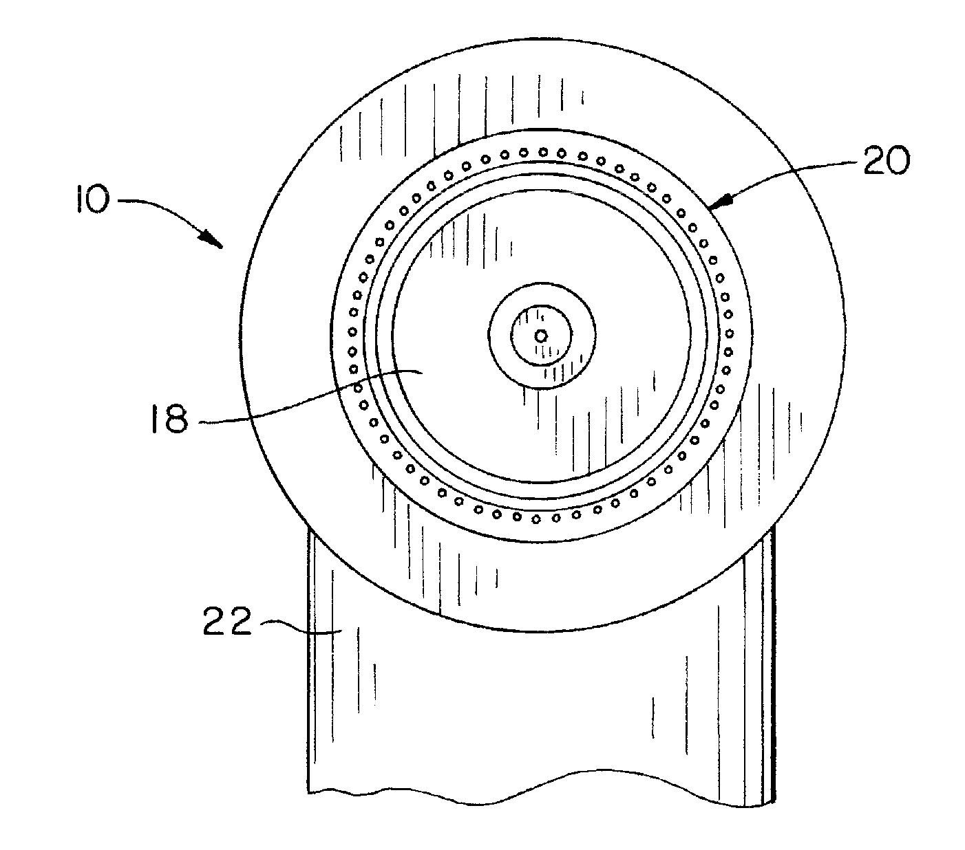
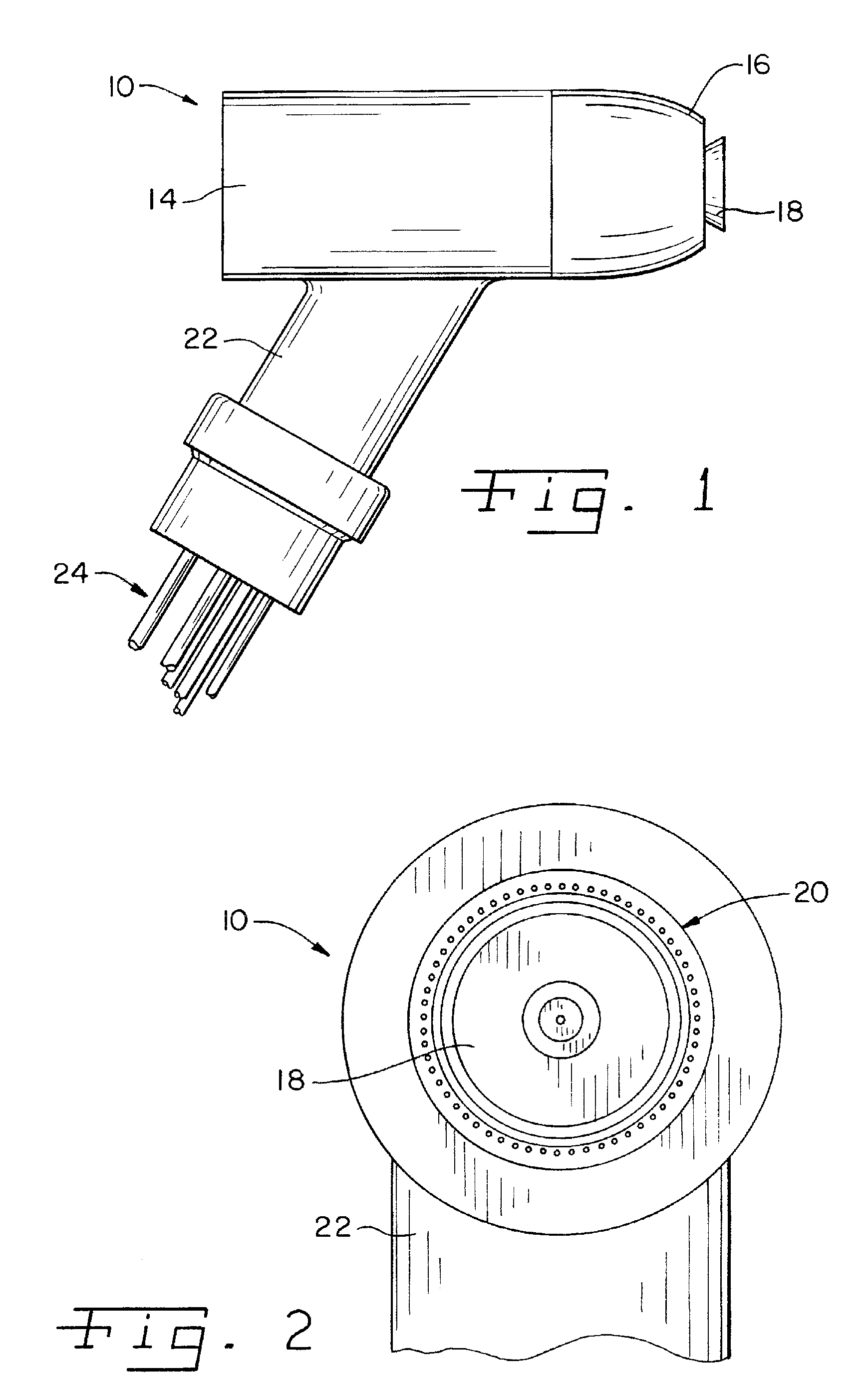
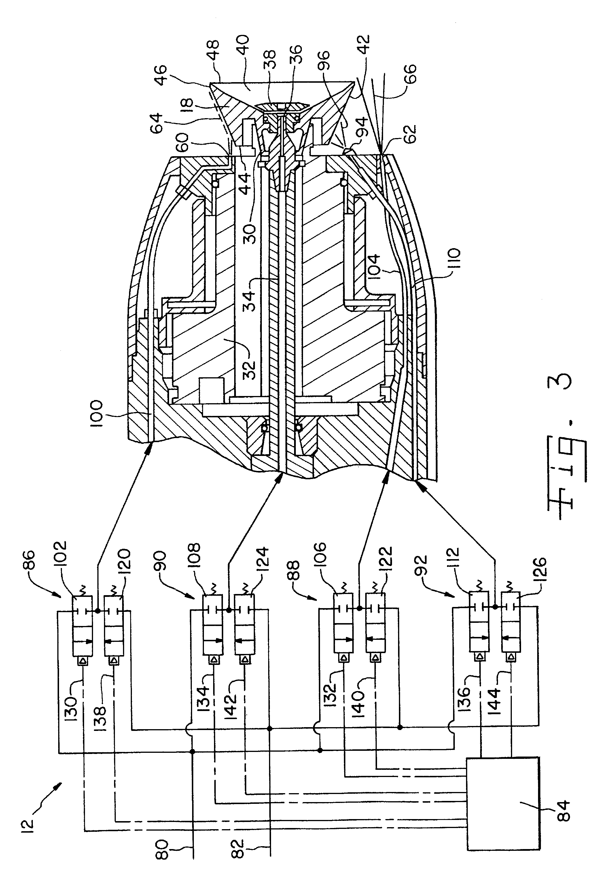
[0021]Referring now more specifically to the drawings and to FIG. 1 in particular, numeral 10 designates a rotary atomizing coating applicator having a fluids control system 12 (FIG. 3) that cooperate in bell cup cleaning in accordance with the present invention. Those skilled in the art will understand readily that the exemplary applicator 10 shown can be mounted on and operated by a robot (not shown) for performing controlled series of maneuvers to properly and consistently coat a series of objects in a manufacturing process. For example, such applicators are used to paint automobile vehicle bodies. However, applicators of this type also can be used for coating a variety of different objects with paint and other coatings. It should be further understood that the present invention works well with different styles and types of applicators and applicator 10 shown is merely one example of such a device. For example, the present invention can be used on applicators that are hand operat...


PUM

PropertyMeasurementUnit
speedaaaaaaaaaa
electrical potentialaaaaaaaaaa
diametersaaaaaaaaaa

Abstract

A spray applicator cleaning system and a method includes a valve and control means for discharging air and solvent in alternating bursts to shaping air nozzles, a coating supply conduit and a dedicated cleaning nozzle on the applicator.

Description

CROSS-REFERENCE TO RELATED APPLICATIONS[0001]This Non-Provisional Application claims the benefit of U.S. Provisional Application No. 60 / 840,083 filed Aug. 25, 2006.FIELD OF THE INVENTION[0002]The present invention relates generally to coating applicators and, more particularly, the present invention relates to cleaning systems and methods for cleaning rotary atomizing applicators used to apply paint and other coatings.BACKGROUND OF THE INVENTION[0003]Spray applicators are used to apply coatings of various types on objects during manufacture. Automobile vehicle bodies commonly are coated using robotic devices with spray applicators. The robot is programmed to perform a sequence of maneuvers and adjustments so that the vehicle body pieces are adequately and precisely covered in a rapid procedure with minimal coating waste.[0004]Atomizing applicators are used to reduce the amount of over spray and further reduce waste. In a known atomizing applicator, a bell cup rotates at high speed, ...

Claims


Application Information

Patent Timeline
Patent Type & Authority Applications(United States)
IPC IPC(8): B08B7/00B05B5/16B08B9/027
CPCB05B3/1014B05B3/1064B05B3/1092B05B13/0431B05B13/0452B05B15/025B05B15/0258B05B15/55B05B15/555
Inventor SEITZ, DAVID M.CEDOZ, ROGER T.
Owner ILLINOIS TOOL WORKS INC
Why Eureka
Try Eureka