Tab lead soldering apparatus and tab lead soldering method

a technology of tab lead and soldering apparatus, which is applied in the direction of soldering apparatus, manufacturing tools,auxillary welding devices, etc., can solve the problems of soldering failure, cell fracture, and difficulty in maintaining the temperature conditions of front and rear faces of solar cells to be the same,

Inactive Publication Date: 2008-02-28
NPC INC
View PDF1 Cites 14 Cited by
  • Summary
  • Abstract
  • Description
  • Claims
  • Application Information

AI Technical Summary

Benefits of technology

[0015] According to the present invention, since the ends of the heat members contact with the tab leads on the front and rear faces of the solar cell, soldering is performed in the same condition on the front and rear faces of the solar cell. Further, since the tab leads can surely be pressed to the front face and the rear face of the solar cell, the tab leads are soldered to the solar cell surely and efficiently. Furthermore, since the heat members are separated from the tab lead as pressing the tab leads by the support members, the tab lead will not be pulled by the heat members when the heat members are separated from the tab lead. Accordingly, a positional displacement of the tab leads or a soldering failure to the front and rear faces of the solar cell can be prevented.

Problems solved by technology

According to the soldering method disclosed in Japanese Patent Application Laid-Open No. 2005-236235, efficient manufacturing can be performed by simultaneously soldering tab leads to the front and rear faces of the solar cell; however, it is difficult to maintain the temperature conditions of the front and rear faces of the solar cell to be the same when the tab leads are simultaneously soldered.
When such a difference in temperate on the front and rear faces of the solar cell occurs, a deformation of the solar cell is generated and this courses a soldering failure.
Further, a fracture of the cell may occur due to heat stress generated in the solar cell.
Further, in case that the tab lead is pulled by the abut member, the connecting strength of the soldering between the tab leads and the front and rear faces of the solar cell may be weakened.

Method used


Image

  • Tab lead soldering apparatus and tab lead soldering method
  • Tab lead soldering apparatus and tab lead soldering method
  • Tab lead soldering apparatus and tab lead soldering method

Examples


Embodiment Construction

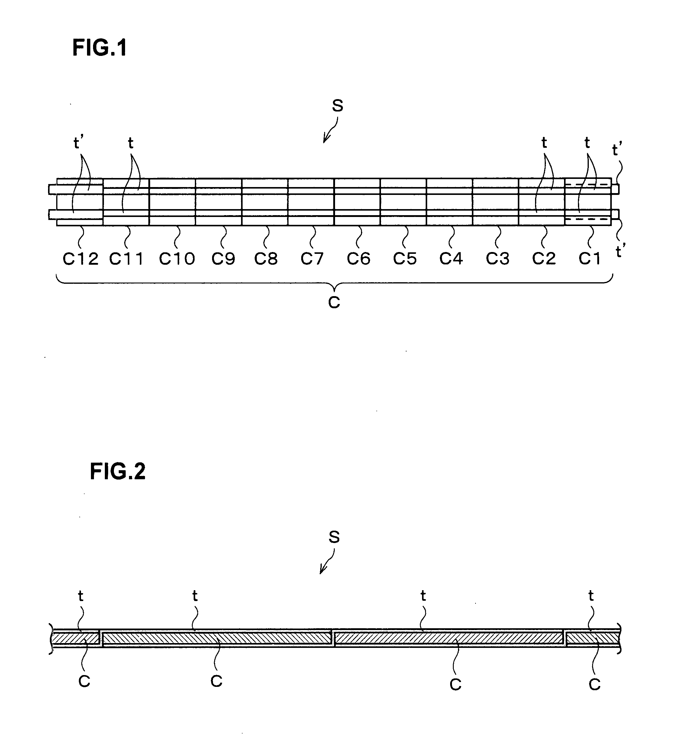
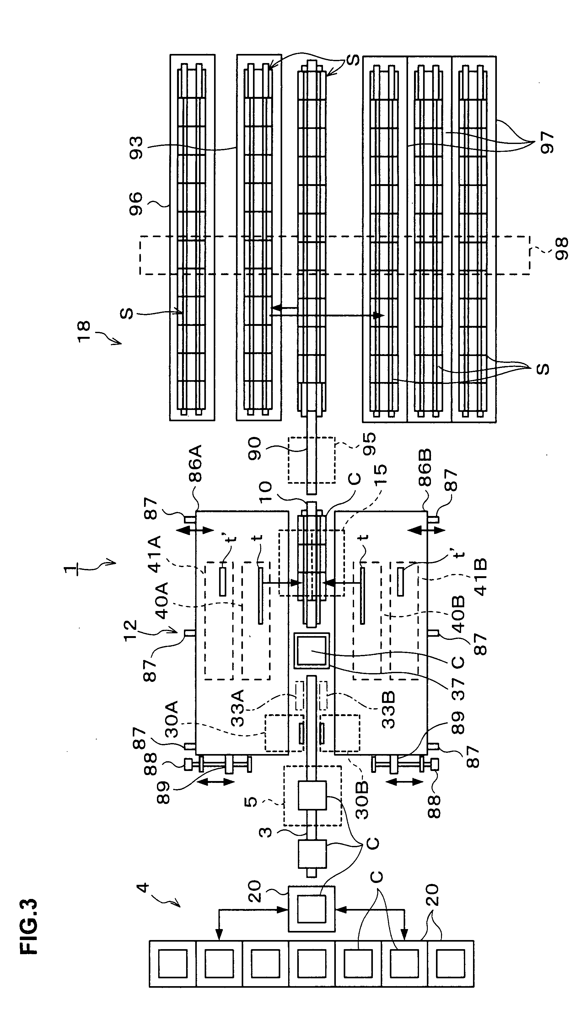
[0030] Preferred embodiments of the present invention will be described. As shown in FIG. 1, a string S is composed of solar cells C for converting solar energy into electrical energy and tab leads t. The plurality of solar cells C, for example, twelve solar cells C, are aligned in series and adjacent solar cells C are electrically connected with two tab leads t, which are arranged in parallel with a predetermined distance. The tab lead t is formed in a long tape-like shape with a predetermined width, for example, width of 2 mm, and the length of the tab lead t is almost equal to the double length of the solar cell C. When connecting adjacent solar cells C, as shown in FIG. 2, a front half portion of the tab lead t (the right portion in FIG. 2) is connected to a front face of the prior solar cell C (in the right side in FIG. 2) and a rear half portion of the tab lead t (the left portion in FIG. 2) is connected to a rear face of the subsequent solar cell C (in the left side in FIG. 2...


PUM

PropertyMeasurementUnit
widthaaaaaaaaaa
widthaaaaaaaaaa
lengthaaaaaaaaaa

Abstract

A tab lead soldering apparatus soldering a tab lead to a front face and a rear face of a solar cell has a first pressing mechanism pressing the tab lead toward the front face of the solar cell, a second pressing mechanism pressing the tab lead toward the rear face of the solar cell rear face, a heat member and a support member provided to the first pressing mechanism and/or the second pressing mechanism to contact with the tab lead, a heat member shift mechanism shifting the heat member between a contact position to contact an end of the heat member with the tab lead and a separation position to separate the end of the heat member from the tab lead, and a support member shift mechanism shifting the support member between a contact position to contact an end of the support member with the tab lead and a separation position to separate the end of the support member from the tab lead.

Description

BACKGROUND OF THE INVENTION [0001] 1. Field of the Invention [0002] The present invention relates to an apparatus and a method for soldering a tab lead to a solar cell in a solar battery manufacturing process. [0003] 2. Description of the Related Art [0004] Conventionally, a solar cell module formed by arranging solar cells in a form of matrix, which convert solar energy into electrical energy, is known. This solar cell module is manufactured by a step of forming strings by arranging solar cells, which are in approximately square thin plate shape, in a line and electrically connecting adjacent solar cells, a step of forming a matrix by arranging the strings in parallel and electrically connecting the strings, and a step of covering the front face (light-receiving face) of the matrix with a cover glass and laminating the rear face of the matrix with a protection material (laminate material). [0005] In the step of forming strings, long tape-like tab leads are connected to front face e...

Claims


Application Information

Patent Timeline
Patent Type & Authority Applications(United States)
IPC IPC(8): A47J36/02
CPCB23K1/0008Y02E10/50H01L31/188
Inventor CHIKAKI, YOSHIRO
Owner NPC INC
Why Eureka
Try Eureka