Surface mounted infrared image detector systems and associated methods

a detector system and infrared image technology, applied in the field of infrared image detector systems, can solve the problems of inability to manufacture and maintain, inability to use surface mount technology, and inability to vacuum seal the infrared image detector array, etc., and achieve the effect of less manufacturing and maintenance costs and more reliable results

Active Publication Date: 2008-02-28
L3 TECH INC
View PDF17 Cites 26 Cited by
  • Summary
  • Abstract
  • Description
  • Claims
  • Application Information

AI Technical Summary

Benefits of technology

[0005]An infrared image detector system and associated methods are disclosed for mounting infrared image detector arrays on printed circuit boards (PCBs) for use with infrared imaging systems such as an infrared camera. A semiconductor die having an infrared detector array and connection points on a first surface is mounted to a PCB and electrically coupled to electrical connection points on a PCB. In addition, a heat sink can be coupled to an opposing second surface of the semiconductor die. Still further, the PCB can have a window within which the infrared image detector array can be positioned so that the infrared image detector system can be mounted to one side of the PCB while infrared radiation incident on the second side of the PCB will reach the infrared image detector array through the window. Mounting an infrared image detector system to a PCB provides a more reliable system that is less costly to manufacture and maintain. As described herein, various different embodiments and configurations may be implemented, as desired.

Problems solved by technology

Many infrared image detectors require a vacuum package that makes the use of surface mount technology impractical.
Thus, surface mount technology has traditionally been considered incompatible with and has not been used for vacuum-sealed infrared image detector arrays.
These thin ribbon connector conductors, however, are vulnerable to damage incurred by excessive flexing, and can be cumbersome.

Method used


Image

  • Surface mounted infrared image detector systems and associated methods
  • Surface mounted infrared image detector systems and associated methods
  • Surface mounted infrared image detector systems and associated methods

Examples


embodiment 500

[0022]FIG. 5 shows a further alternate embodiment 500 of an infrared detector system 200 mounted to a printed circuit board (PCB) 301 using a die clamp 501 and using flexible leads 405 and / or lead frames to provide electrical connection between the semiconductor die 202 and the PCB 301. In FIG. 5, the plurality of connection points 205 on the semiconductor die 202 are connected with lead wires 405 to connection points on the PCB 301. It is noted that in this embodiment as depicted, connection points 205 are located on one side of the semiconductor die 202, but could be located on two or more sides, as desired. As with FIGS. 3 and 4, a heat sink 201 is coupled to back opposing surface 212 of the semiconductor 202. The infrared detector array 203 is formed on the front surface 210 of the semiconductor die 202. The lid 204 is again covering the infrared detector array 203. Unlike FIGS. 3 and 4, however, traditional surface mount techniques and spacers 305 are not used to provide the el...

embodiment 600

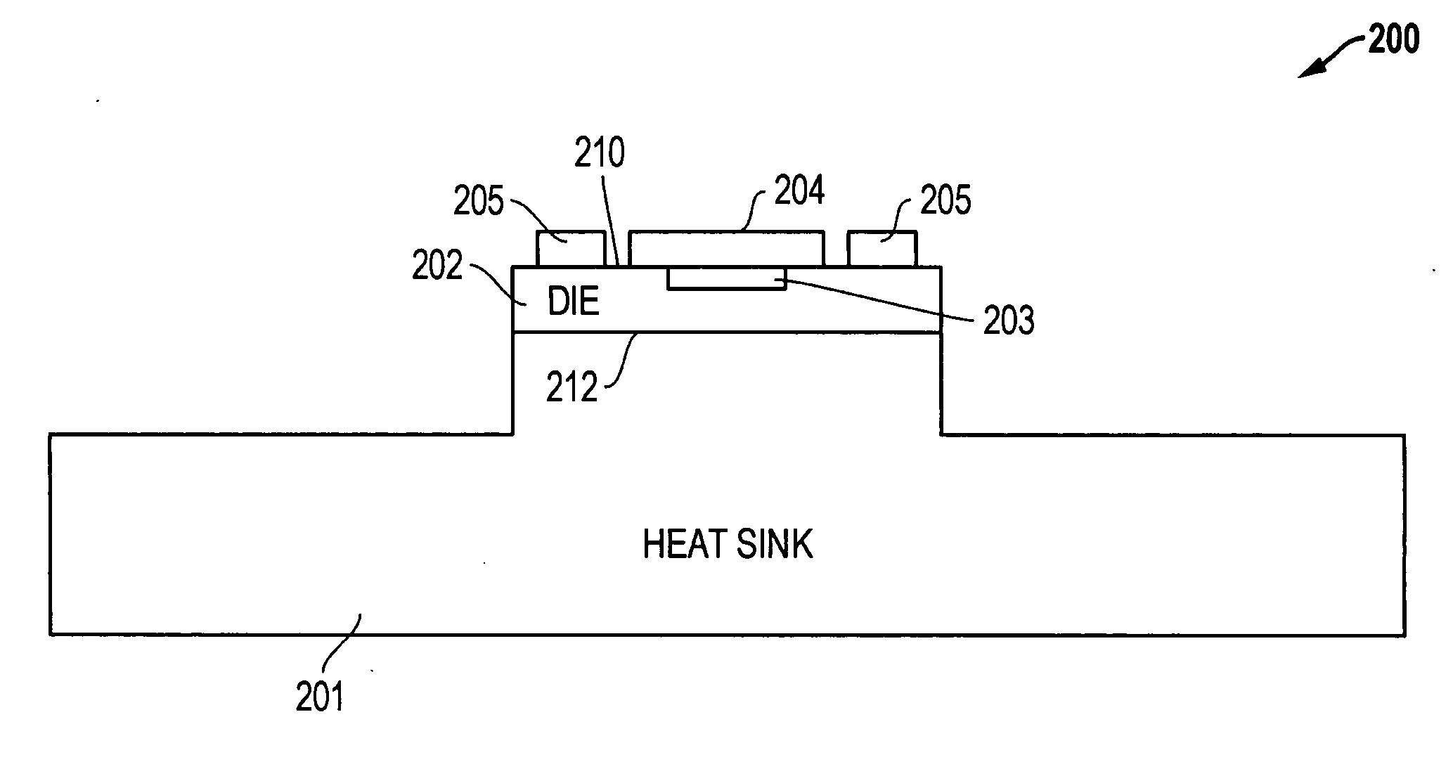
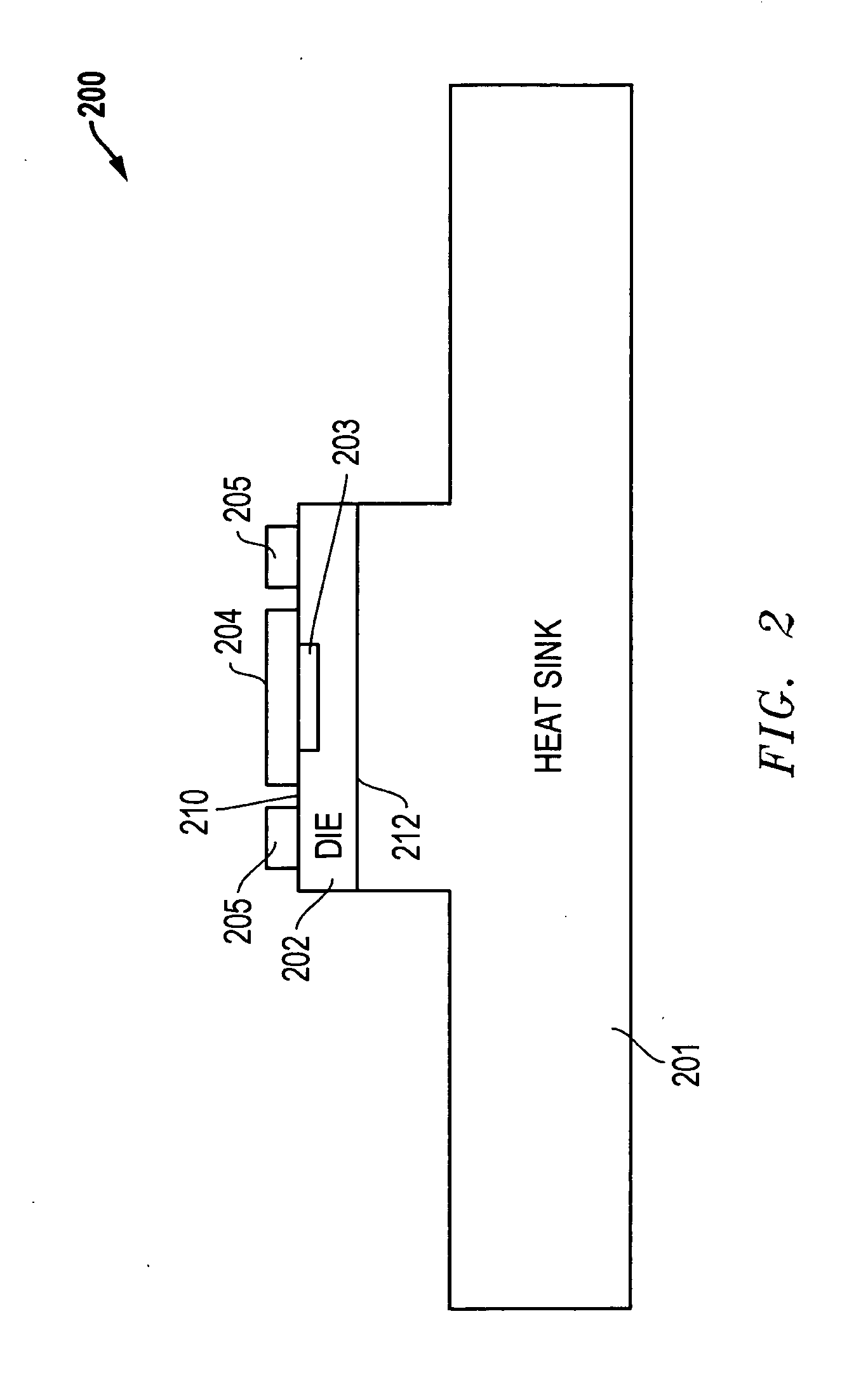
[0023]FIG. 6 shows an alternate embodiment 600 of an infrared detector system 200 mounted to a printed circuit board (PCB) without having a separate heat sink 201. As with FIG. 3, the infrared detector array 203 is formed on the front surface 210 of the semiconductor die 202. The lid 204 is again covering the infrared detector array 203. Unlike FIG. 3, traditional surface mount techniques are not used to provide the electrical and mechanical connections. Rather the semiconductor die 202 is directly mounted on to the PCB 301. And the connection points 205 are coupled to the PCB 301 using standard bond wires. In addition, the heat sinking capabilities of PCB 301 under die 212 could be enhanced, if desired, by adding copper traces to PCB 301. Other variations could be implemented as desired.


PUM


Abstract

An infrared image detector system mounted on a printed circuit board (PCB) is disclosed for use with an infrared imaging system such as an infrared camera. A semiconductor die having an infrared detector array and connection points on a first surface is mounted to a PCB and electrically coupled to electrical connection points on a PCB. In addition, a heat sink can be coupled to an opposing second surface of the semiconductor die. Still further, the PCB can have a window within which the infrared image detector array can be positioned so that the infrared image detector system can be mounted to one side of the PCB while infrared radiation incident on the second side of the PCB will reach the infrared image detector array through the window.

Description

TECHNICAL FIELD OF THE INVENTION [0001]This invention relates to infrared image detector systems and, more particularly, to infrared image detector systems utilized for infrared cameras or other infrared devices.BACKGROUND [0002]Technology has existed to connect integrated circuits to printed circuit boards (PCBs). Known previously are various forms of surface mount technology, such as “chip on board” technology, wherein a semiconductor die is glued to a printed circuit board (PCB), wire bonded, and covered with a drop of epoxy. Another known surface mount technique is a “flip chip” technology, wherein a semiconductor die is inverted and connected by various forms of extensions of its bond pads directly to electrical connection points or pads on the PCB. In some systems, ceramic packages have lead frames which are soldered to the PCB. Other forms of current surface mount technology include inverting a semiconductor die onto the PCB and using solder pads distributed over the upper de...

Claims


Application Information

Patent Timeline
Patent Type & Authority Applications(United States)
IPC IPC(8): G01J5/20
CPCG01J5/10H01L27/14649H01L31/0203H01L31/024H04N5/2253H01L2224/48227H04N5/33H01L2224/48091H01L2924/00014H04N23/54
Inventor GOOCH, ROLAND W.
Owner L3 TECH INC
Why Eureka
Try Eureka