Piezoelectric Resonator and Method for Producing the Same

a resonator and piezoelectric technology, applied in piezoelectric/electrostrictive/magnetostrictive devices, piezoelectric/electrostriction/magnetostriction machines, impedence networks, etc., can solve the problem of ineffective suppression of unnecessary vibrations generated by the gradient of frequency constant of piezoelectric substrates, and inability to achieve precise resonant frequency, etc. problem, to achieve the effect of suppressing unnecessary in-band

Inactive Publication Date: 2008-02-28
MURATA MFG CO LTD
View PDF5 Cites 11 Cited by
  • Summary
  • Abstract
  • Description
  • Claims
  • Application Information

AI Technical Summary

Benefits of technology

[0016] Accordingly, it is an object of the preferred embodiments of the present invention to provide a piezoelectric resonator for achieving a precise resonant frequency by reducing frequency variations caused by differences in frequency constant in the case of a piezoelectric substrate whose thickness is constant and whose frequency constant has a gradient, suppressing unnecessary vibrations generated by the gradient of frequency constant of the piezoelectric substrate, and achieving the stable resonant frequency, and a method of producing the same. Means for Solving the Problems

Problems solved by technology

When a frequency constant varies in the piezoelectric substrate, a precise resonant frequency cannot be achieved.
Unnecessary vibrations generated by the gradient of frequency constant of the piezoelectric substrate cannot be suppressed.
In the method described in Patent Document 3 in which the thickness of the piezoelectric substrate is changed with a constant gradient while the thickness of the electrodes has a gradient in the opposite direction, unnecessary vibrations resulting from the gradient of frequency constant cannot be effectively suppressed.

Method used


Image

  • Piezoelectric Resonator and Method for Producing the Same
  • Piezoelectric Resonator and Method for Producing the Same
  • Piezoelectric Resonator and Method for Producing the Same

Examples


embodiment 1

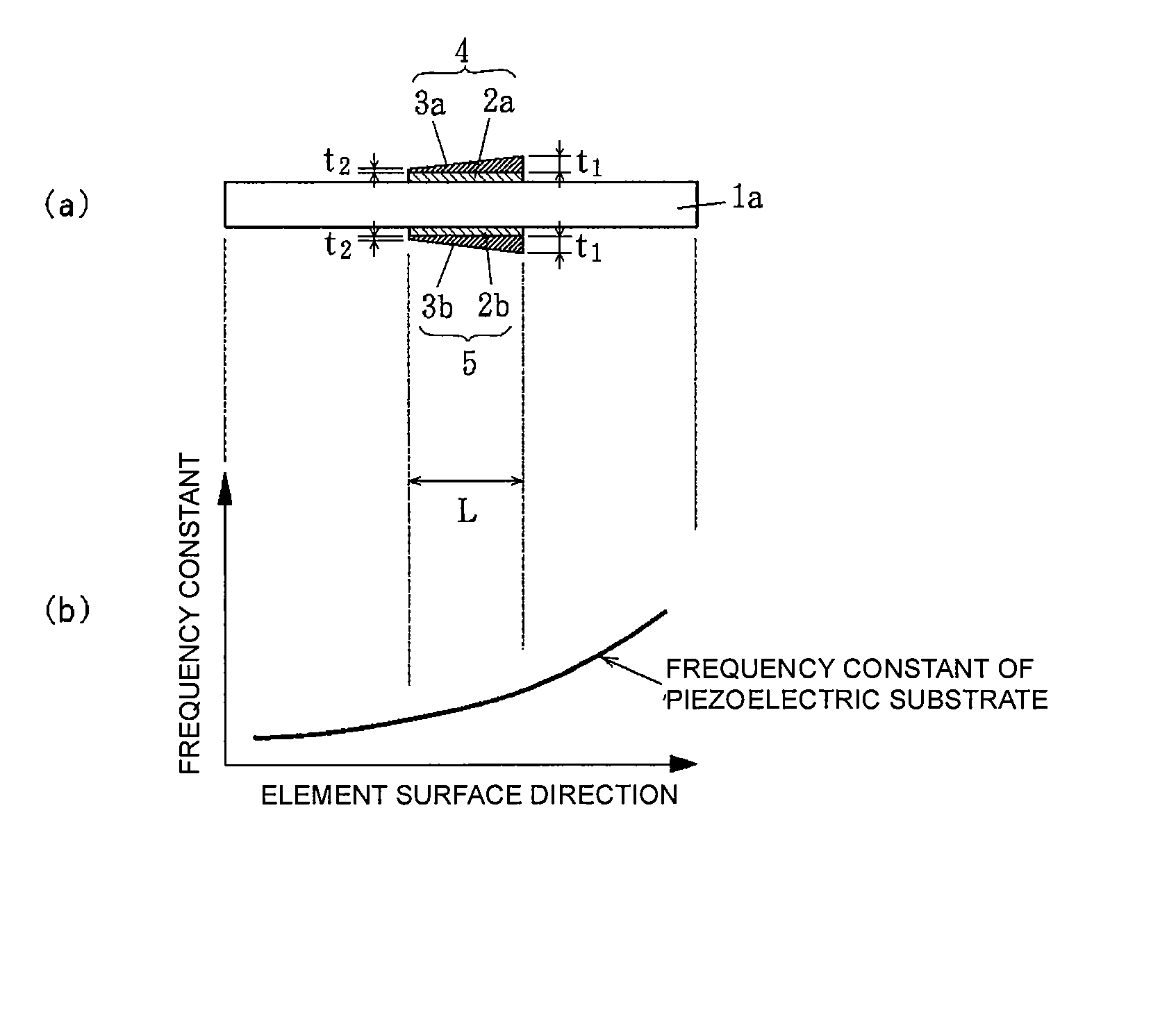
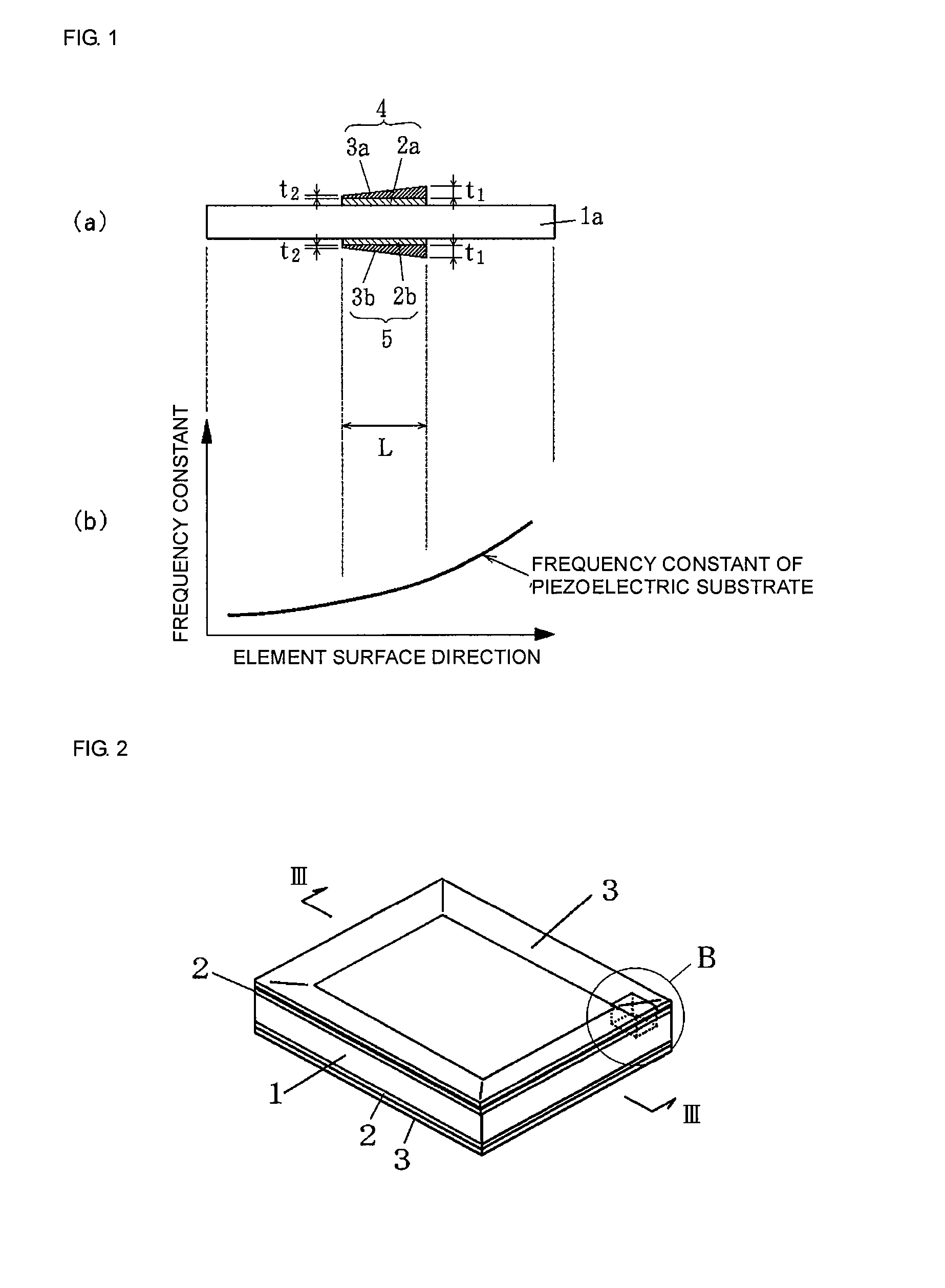
[0051]FIG. 1(a) shows a first embodiment of a piezoelectric resonator according to the present invention. The piezoelectric resonator is an energy-trapped piezoelectric resonator in a thickness-longitudinal vibration mode.

[0052] The piezoelectric resonator includes a rectangular piezoelectric substrate 1a formed of a piezoelectric ceramic, such as a lead zirconate titanate ceramic or a lead titanate ceramic. The piezoelectric substrate 1a is polarized in a thickness direction. The resonant frequency of the piezoelectric resonator depends on its thickness. When the thickness is 0.475 mm, the resonant frequency is 16 MHz.

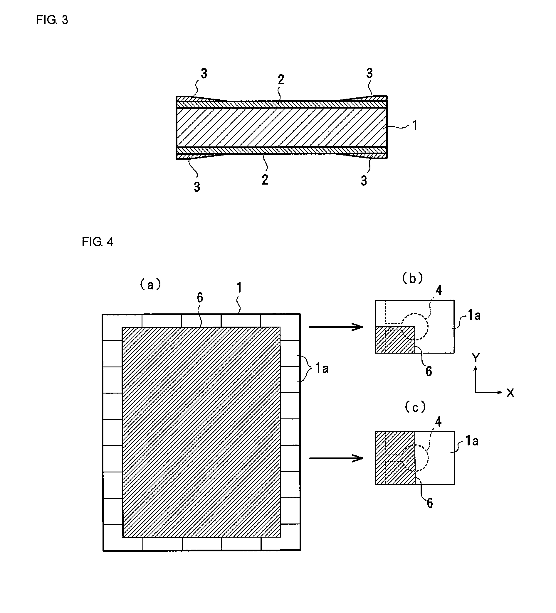
[0053] Vibrating electrodes 4 and 5 facing each other are formed at the center of front and back surfaces of the piezoelectric substrate 1a. Although not shown in FIG. 1, extraction electrodes extracted from the vibrating electrodes 4 and 5 to the periphery of the piezoelectric substrate 1a and terminal electrodes are formed on the front and back surfaces of the pie...

embodiment 2

[0074] FIGS. 10(a) to (c) show another embodiment of electrode structures of the piezoelectric resonator according to the present invention.

[0075]FIG. 10(a) shows the case in which the vibrating electrodes 4 and 5 with a gradient thickness have a single-layer structure. As a layer underlying the vibrating electrodes 4 and 5, an alloy layer formed of Ni, Cr, and the like may be used to enhance the adhesion to the piezoelectric substrate (ceramic).

[0076]FIG. 10 (b) shows the case in which the vibrating electrode 4 disposed on the front surface has a gradient thickness, whereas the vibrating electrode 5 disposed on the back surface has a constant thickness. In this case, let t3 be the thickness of the thickest portion of the vibrating electrode 4 disposed on the front surface, t4 be the thickness of the thinnest portion of the vibrating electrode 4, and L be the length of the vibrating electrode 4. Then, it is preferable that the thickness gradient ratio (t3−t4) / L=0.10 to 0.40. That ...


PUM


Abstract

To reduce frequency variations caused by a change in frequency constant and suppress unnecessary vibrations in the case where the frequency constant of a piezoelectric substrate has a gradient. A piezoelectric resonator has vibrating electrodes 4 and 5 facing each other, which are formed on two major surfaces of a piezoelectric substrate 1a, and trapped vibrations are generated between the two vibrating electrodes. The piezoelectric substrate 1a has a constant thickness. The frequency constant of the piezoelectric substrate 1a has a gradient in a surface direction. The vibrating electrodes 4 and 5 are formed to have a gradient thickness so that the thickness gradually increases as the frequency constant of the piezoelectric substrate increases. By forming the vibrating electrodes to have a gradient thickness, unnecessary in-band vibrations are suppressed, and frequency variations are reduced.

Description

CROSS REFERENCE TO RELATED APPLICATIONS [0001] The present application is a continuation of International Application No. PCT / JP2006 / 301102, filed Jan. 25, 2006, which claims priority to Japanese Patent Application No. JP2005-025248, filed Feb. 1, 2005, the entire contents of each of these applications being incorporated herein by reference in their entirety.TECHNICAL FIELD [0002] The present invention relates to a piezoelectric resonator which has vibrating electrodes facing each other formed on two major surfaces of a piezoelectric substrate and which is used to generate vibration strapped between the two vibrating electrodes, and a method for producing the same. BACKGROUND ART [0003] In general, the production of piezoelectric resonators involves baking, molding, and polarization of a piezoelectric substrate 1 serving as a mother substrate (unit), as shown in FIG. 11. An electrode 2 with a constant thickness is formed by sputtering or vapor deposition on the entire front and back...

Claims


Application Information

Patent Timeline
Patent Type & Authority Applications(United States)
IPC IPC(8): H01L41/00H01L41/09H01L41/187H01L41/22H01L41/29H03H3/02H03H9/17
CPCH03H3/04H03H9/02086H03H9/13H03H2003/0428H03H9/132H03H9/176H03H9/131
Inventor YOSHIO, MASAKAZUYAMASAKI, KOICHI
Owner MURATA MFG CO LTD
Why Eureka
Try Eureka