Discharge Lamp Lighting Apparatus and Projector

Inactive Publication Date: 2008-02-28
MATSUSHITA ELECTRIC WORKS LTD
View PDF10 Cites 28 Cited by
  • Summary
  • Abstract
  • Description
  • Claims
  • Application Information

AI Technical Summary

Benefits of technology

[0013] According to the prevent invention, in the discharge lamp lighting apparatus which uses, as a lighting power source, a power source section which rectifies and smoothes commercial a.c. power, a voltage ripple in power

Problems solved by technology

However, to win in the growing market how to deal with a flicker of light from a lamp is becoming an important issue.
This gives rise as a side effect to a problem that depending upon the temperature of an electrode of the high-pressure discharge lamp and the condition of a surface of the electrode which is near an arc, a discharge arc develops at an instable location on the electrode and to a phenomenon that the origin of

Method used


Image

  • Discharge Lamp Lighting Apparatus and Projector
  • Discharge Lamp Lighting Apparatus and Projector
  • Discharge Lamp Lighting Apparatus and Projector

Examples


Example

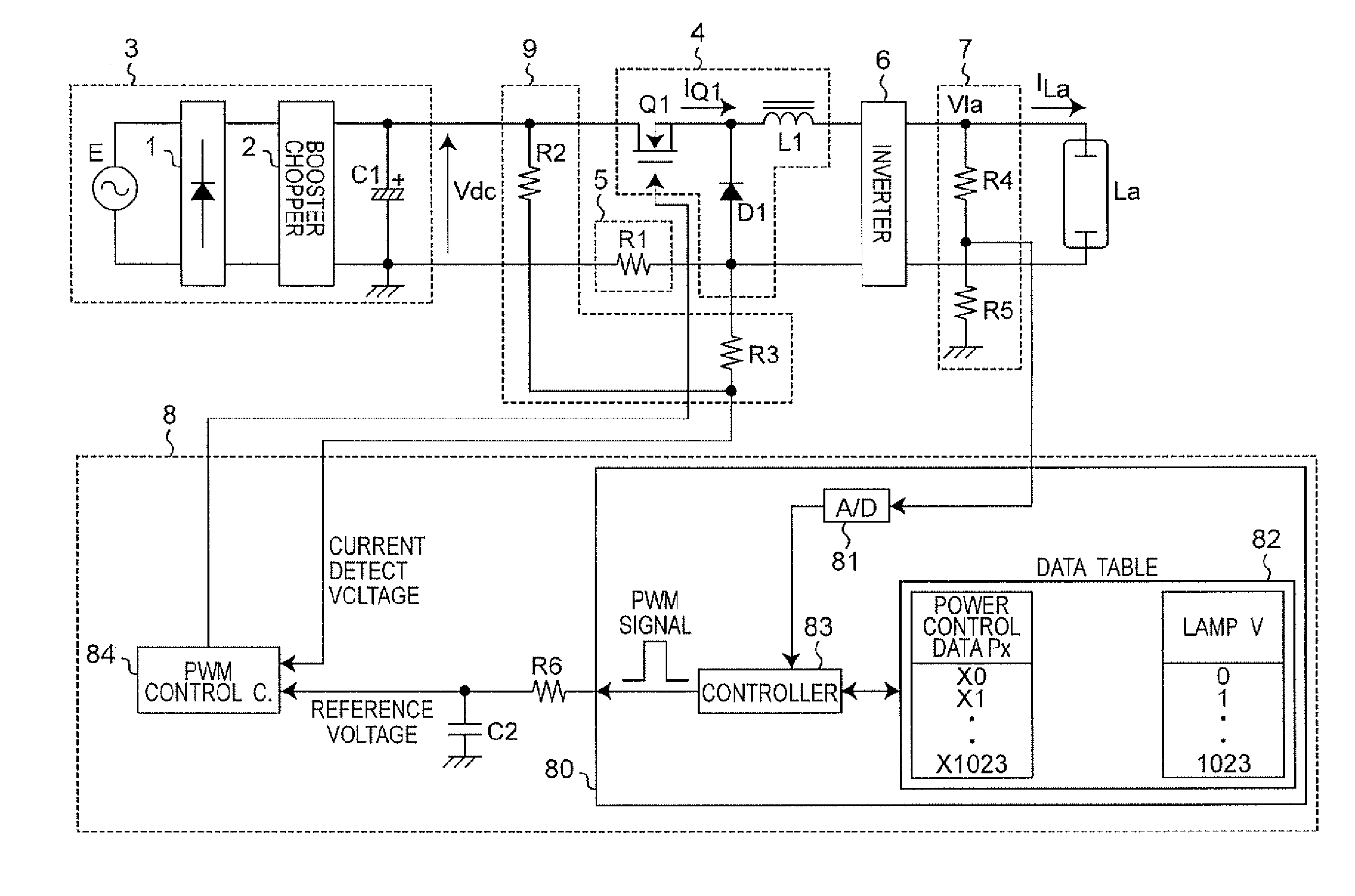
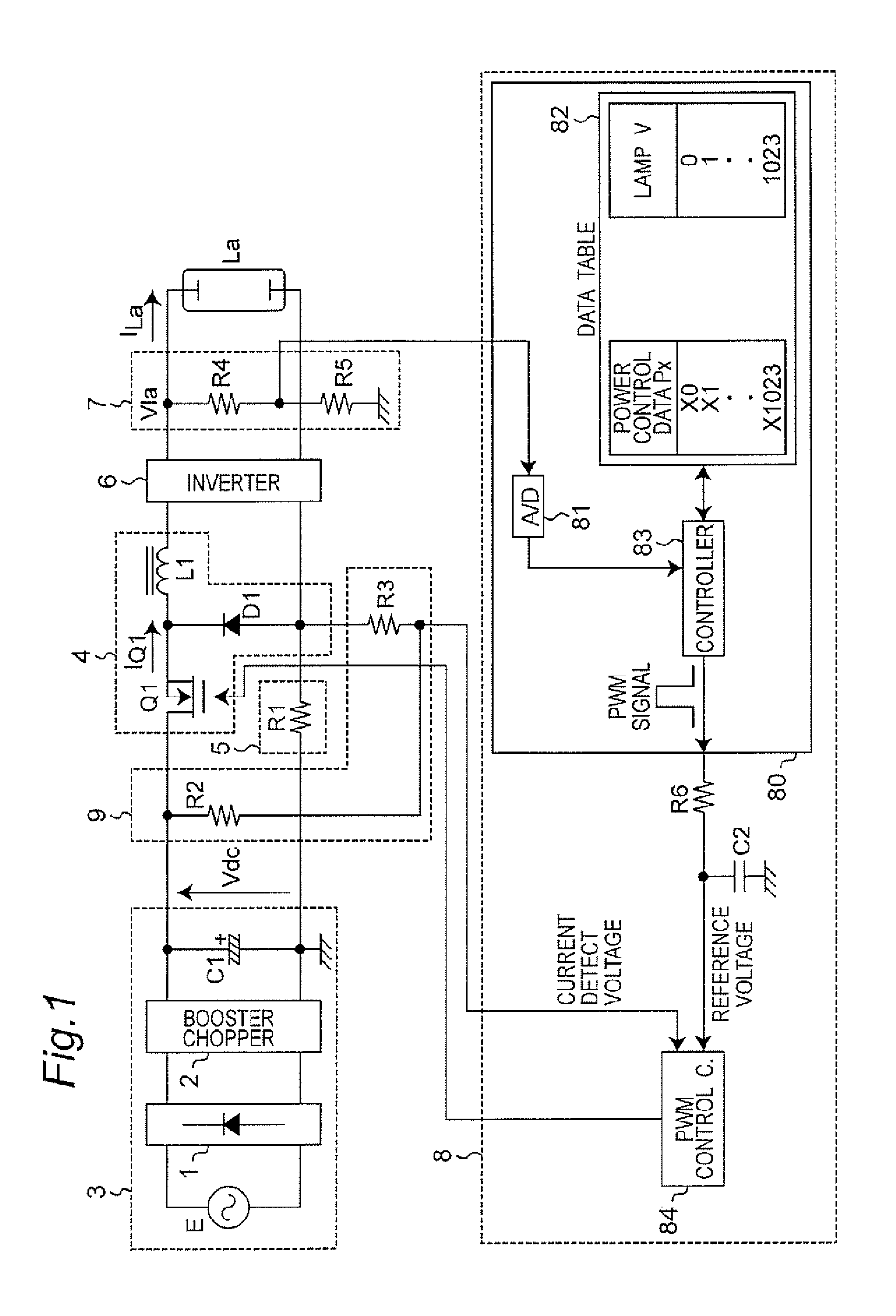
[0031]FIG. 1 is a circuitry diagram which shows the first embodiment of the present invention. The discharge lamp lighting apparatus shown in FIG. 1 includes a d.c. power source section 3 which outputs a d.c. voltage Vdc which is obtained by rectifying and smoothing a voltage from a commercial a.c. power source E, a step-down chopper circuit 4 which is connected with an output terminal of the power source section 3 and which provides power control of a discharge lamp La, a discharge lamp current detecting circuit 5 which detects a current flowing through the discharge lamp La, an invertor circuit 6 which inverts the polarity of a voltage of the discharge lamp La at a low frequency and which accordingly lights up the lamp with a rectangle wave, a discharge lamp voltage detecting circuit 7 which detects a voltage applied upon the discharge lamp La, a control circuit block 8 which provides power control, and a power source ripple detecting circuit 9 which is formed by power source ripp...

Example

Second Embodiment

[0046]FIG. 5 is a circuitry diagram which shows the second embodiment of the present invention. The discharge lamp lighting apparatus according to this embodiment is different from the discharge lamp lighting apparatus according to the first embodiment shown in FIG. 1 with respect to the structures of the power source ripple detecting circuit 9 and the control circuit block 8.

[0047] The control circuit block 8 in the discharge lamp lighting apparatus according to this embodiment: includes the microcomputer 80, the PWM control circuit 84, a voltage addition circuit 85 and a phase control circuit 86.

[0048] The power source ripple detecting circuit 9 is formed by a series circuit of the resistor R2 and the resistor R3 which are connected between a high-voltage side output terminal and a low-voltage side output terminal of the d.c. power source section 3, and the control circuit block 8 directly receives a voltage which the resistor R2 and the resistor R3 generates b...

Example

Third Embodiment

[0053]FIG. 9 is a circuitry diagram which shows the third embodiment of the present invention. This embodiment demands control for switching a rate of superimposition of the detect voltage of power in accordance with the discharge lamp voltage. The discharge lamp lighting apparatus according to this embodiment is different from the discharge lamp lighting apparatus according to the second embodiment in terms of the structure of the control circuit block 8. The control circuit block 8 according to this embodiment includes the microcomputer 80, the PWM control circuit 84 and the voltage addition circuit 85.

[0054] In the data table 82 inside the microcomputer 80, the discharge lamp voltage, the lighting power Px and voltage ripple superimposition data Vxx are stored in correlation to each other. In the data table 82, the power control data Px is a power control data command value (X0, X1, . . . , X1023) in response to the detected lamp voltage value (0, 1, . . . , 102...


PUM


Abstract

A discharge lamp lighting apparatus comprising a d.c. power source section which rectifies and smoothes an a.c. voltage; a current detecting circuit which detects a current which flows through a discharge lamp; a power source ripple detecting circuit which detects a voltage change of power supplied from the d.c, power source section and outputs a voltage obtained by superimposing the detected voltage over a detected voltage which is available from the current detecting circuit; and a control circuit which controls, based on) the output voltage from the power source ripple detecting circuit, an output voltage to the discharge lamp so that the current flowing through the discharge lamp becomes a constant current. A rate of superimposition of the output voltage from the power source ripple detecting circuit may be switched in accordance with the discharge lamp voltage.

Description

TECHNICAL FIELD [0001] The present invention relates to a discharge lamp lighting apparatus which uses, as a lighting power source, a power source which rectifies and smoothes commercial a.c. power and more particularly, to a technique for controlling a discharge lamp current constant BACKGROUND ART [0002] The recent years have seen a rapid expansion of a projectors market and a further market growth is expected. However, to win in the growing market how to deal with a flicker of light from a lamp is becoming an important issue. Brightness has been one of criteria for determining whether a light source for a projector has a superior capability, and a high-pressure mercury-arc lamp developed noting this has a shortest possible arc length and resembles as much as possible a point light source in an effort to enhance the luminance. This gives rise as a side effect to a problem that depending upon the temperature of an electrode of the high-pressure discharge lamp and the condition of a...

Claims


Application Information

Patent Timeline
IPC IPC(8): H05B41/36H05B41/24H05B41/282H05B41/288
CPCH05B41/2883
Inventor HASEGAWA, JUNICHIKONISHI, HIROFUMIKISHIMOTO, AKIHIROWATANABE, KOJINAKADA, KATSUYOSHI
Owner MATSUSHITA ELECTRIC WORKS LTD
Why Eureka
Try Eureka