Method for contact-free testing of antennas applied to a material web

Inactive Publication Date: 2008-02-28
NORDENIA DEUT GRONAU GMBH
View PDF7 Cites 0 Cited by
  • Summary
  • Abstract
  • Description
  • Claims
  • Application Information

AI Technical Summary

Benefits of technology

[0005]With this background, it is an object of the invention to reduce the costs of the production of RFID labels.
[0008]According to the invention, the measurement antenna arrangement of the measurement device has a high-frequency signal of the transmitter applied to it, and part of the high-frequency power is emitted by the measurement antenna arrangement and absorbed by the antenna to be tested. In this connection, it is practical to select the frequency fmess of the transmitter in such a manner that the antennas to be tested, which lie within pre-determined production tolerances, absorb a maximum of the high-frequency power, thereby also minimizing the high-frequency signal Srück that returns to the connector of the measurement antenna arrangement. In order to determine the power that is assigned to the outgoing high-frequency signal Smess, and the power assigned to the returning high-frequency signal Srück, the high-frequency signal Smess is preferably passed from the transmitter to the measurement antenna arrangement by way of a directional coupler that emits a first measurement signal that is proportional to the high-frequency power Pvor, which runs to the measurement antenna arrangement. The directional coupler emits a second measurement signal that is proportional to the high-frequency power Prück, which is reflected by the measurement antenna arrangement. In practice, the ratio of the power fed in at the transmitter to the power reflected back by the measurement arrangement is also indicated in decibels (dB), as the front-to-back ratio.

Problems solved by technology

The production costs are greatly increased by a high level of rejects, since the entire RFID labels, with their antenna and RFID chip, must be sorted out and disposed of.

Method used


Image

  • Method for contact-free testing of antennas applied to a material web
  • Method for contact-free testing of antennas applied to a material web
  • Method for contact-free testing of antennas applied to a material web

Examples


Embodiment Construction

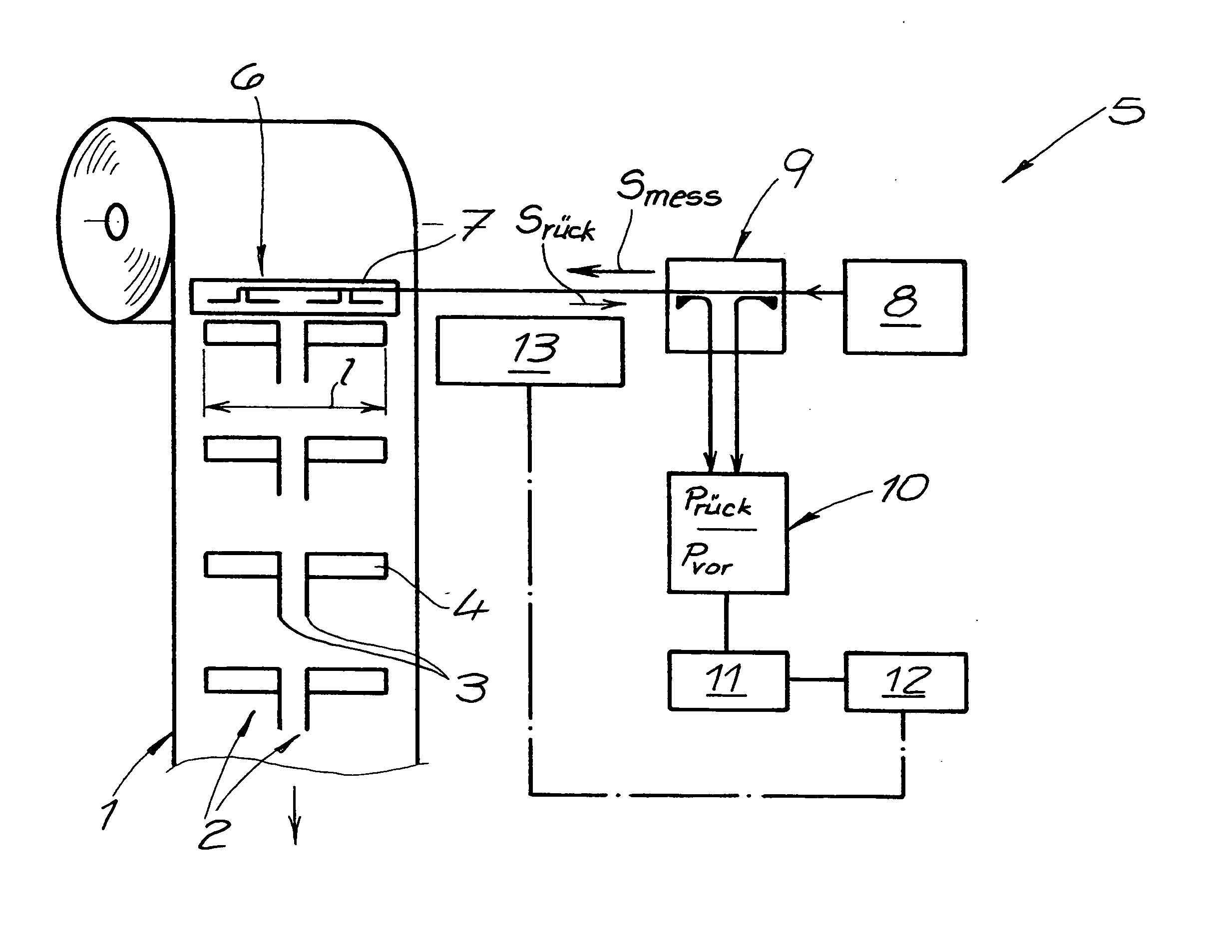
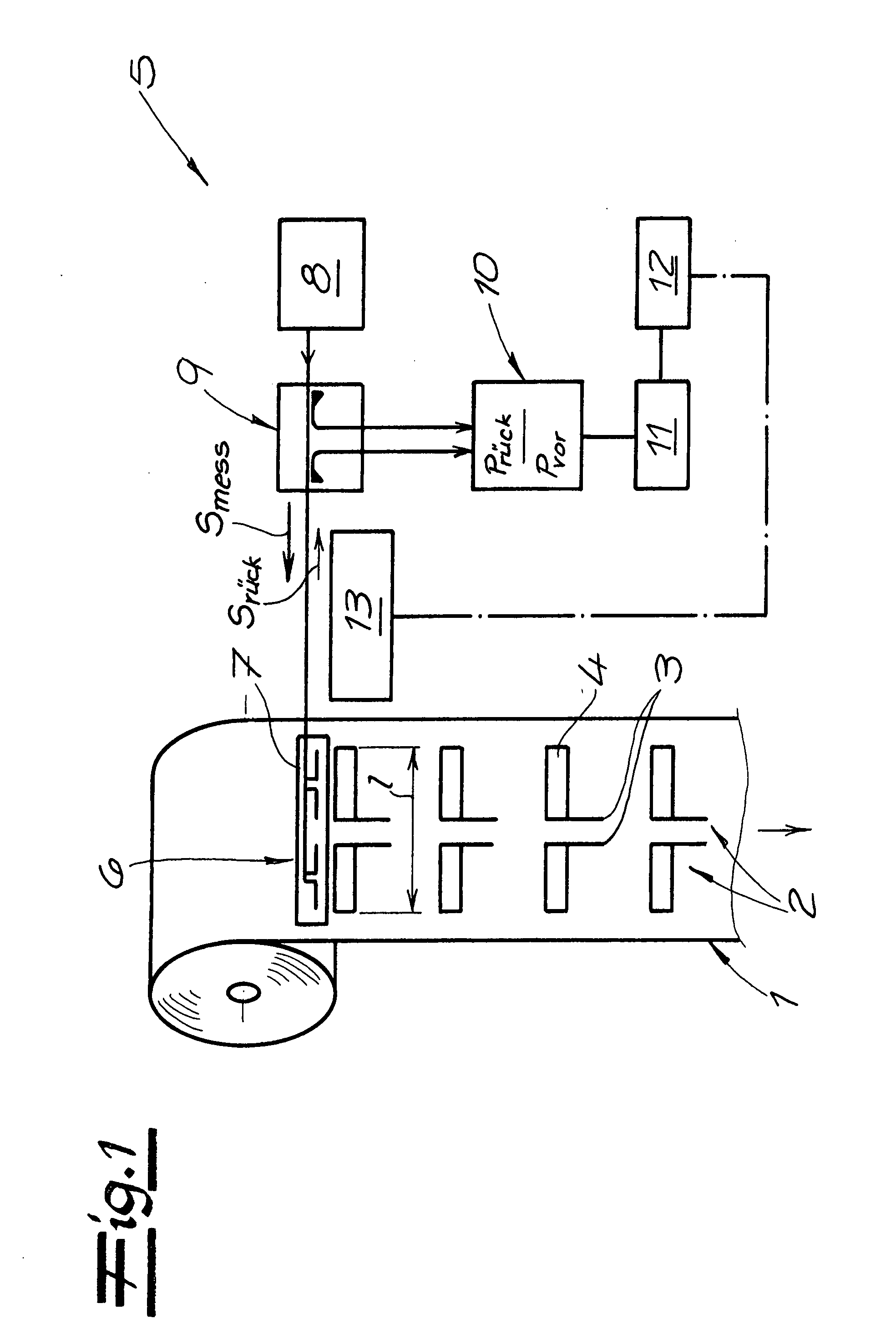
[0021]Referring now in detail to the drawings and, in particular, FIG. 1 shows a material web 1 having antennas 2 for RFID labels applied to it. Antennas 2 are imprinted onto material web 1, which is configured as a polymer film, as half-wave dipole antennas, using a conductive ink and an intaglio printing process. Antennas 2 have two central connector ends 3, from which a rectangular conductive track 4 extends, in each instance. The working frequency fA, which can lie at 900 MHZ, for example, is pre-determined by the total length l of antennas 2, which corresponds to about half the wavelength. Material web 1 with a plurality of antennas 2 is passed to a measurement device 5, and antennas 2 each are passed past an assigned measurement antenna arrangement 6 of measurement device 5 in the region of measurement device 5. In this connection, measurement antenna arrangement 6 has a separate measurement antenna 7 for each of conductive tracks 4. Measurement antennas 7 have a high-frequenc...


PUM


Abstract

A method for contact-free testing of antennas applied to a material web, wherein the material web having the antennas is passed to a measurement device. The antennas are passed past an assigned measurement antenna arrangement of the measurement device in the region of the measurement device and the measurement antenna arrangement has a high-frequency signal Smess of a transmitter applied to it. This signal is correlated with a pre-determined working frequency fA of the antennas. The high-frequency signal Srück that returns from the measurement antenna arrangement is determined and compared with default values, and the adherence to production tolerances is determined by the comparison of the returning high-frequency signal Srück with the default values for each of the individual antennas.

Description

BACKGROUND OF THE INVENTION[0001]1. Field of the Invention[0002]The invention relates to a method for contact-free testing of antennas for RFID labels applied to a material web. RFID labels have not only an antenna but also an RFID chip as an active or passive circuit, and are suitable, for example, for identifying objects of all kinds, such as goods and transport packagings. In the identification of the packaging of mass-produced articles, in particular, only one-time use of an RFID label is generally provided, so that production costs are particularly low.[0003]2. The Prior Art[0004]U.S. Pat. No. 6,147,662 describes a method for the production of RFID labels, wherein an antenna is imprinted onto a material web with conductive ink or with conductive toner, and wherein subsequently, an RFID chip is set onto the antenna and contacted with it. The RFID labels are passed to a measurement device before being wound up into a roll, with defective RFID labels being determined and marked. I...

Claims


Application Information

Patent Timeline
IPC IPC(8): G01R31/01
CPCG01R29/10G01R31/013H01Q1/2208G06K19/0722G01R31/2822H01Q1/24
Inventor KOHLA, MICHAEL
Owner NORDENIA DEUT GRONAU GMBH
Why Eureka
Try Eureka